BELLAS, Leonardo Dias [1]
BELLAS, Leonardo Dias. Binary System 2 – Code Closed. Revista Científica Multidisciplinar Núcleo do Conhecimento. 04 year, Ed. 02, vol. 05, pp. 110-151. February 2019. ISSN: 2448-0959.
1. Presentation
In 2016 a discovery was made on Binary Systems, since then I started to develop a study and research on Binary Systems. I realized that this is a subject in which there is not much information studied, so I decided to unravel a research on Binary Systems.
In this theoretical study I will provide information on the two binary systems, on the binary system we use and on the binary system that was discovered, I will cite technical differences between the two systems and demonstrate the sovereignty of the Binary System 2 before the Binary System 1 .
”CODE CLOSED – BINARY SYSTEM 2.”
2. Introduction
The present discovery is of a new Binary System that here in this Descriptive Report I will cite it as Binary System 2 and its name is CODE CLOSED. What is the Binary System? The computer uses a binary representation to store and manipulate the data. Data in this case, which can be stored programs, images, sounds, texts, videos, among others. The Binary system is a system of numbering formed by only two figures, any information or data of a computer is represented in binary numbers (Zeros and Uns). They are the smallest unit of information possible to be represented digitally.
That is, it only admits two possibilities, always, antagonistic, as: all / nothing; on off; presence / absence; right left; tall short; truth or false; on / off. All digital electronics and computing are based on this binary system and Boolean logic, which allows the representation of numbers, characters, logical and arithmetic operations by digital electronic circuits (logic gates). Computer programs are encoded in binary form and stored in media (memories, discs, etc.) in this format. Thus, for information stored in computer RAM, the format will be of higher voltage (1) or lower voltage (0). In magnetic disks the binarity will be by polarity difference, positive or negative. (Which is where one of the discoveries was made, it was observed that Binary System is an Electromagnetic Circuit, and there is one type of Electromagnetic Circuit for Binary System 1 and another type of Electromagnetic Circuit for Binary System 2. Another finding is also that ZERO is equal to NEUTRAL and 1 (ONE) is equal to the irrational number PI, which in the basic mathematics PI represents the division of a circumference and the corresponding diameter, with an approximate value of 3.14. is the Length of a Wave. In short, Binary System 2 was deciphered in PI.)
It is observed that there is another Binary System beyond what we know and use, where the Binary System II, called “CODE CLOSED, where another Binary Equation Logic is used (where 0 is ZERO and 1 is organized and arranged in a different way from the Binary System 1, and also with different mathematical and physical equations). Becoming much superior, more efficient, effective and safe. It has been discovered that there is another Code, Logic and Binary Equation, where System 2 becomes linear and congruent, as well as differences in the Pixel template (PIXEL ROUND / SPHERE), bringing much more definition of image and graphics, besides many other differences Binary System II, which is a new computer (Generation 2), is a new System of compilation, manipulation, processing, programming and Data storage.
3. Binary System 1 And Binary System 2 And Its Differences
In this descriptive report will be demonstrated and reported differences between the two binary systems, differences in their Codes and Equations and their functionalities before the other system.
All Binary systems are programmed through 8 zeros, a sequential logic of 8 sequences. The first difference is in the Code used in the Binary System 1 if you use the Binary Sequential Code: 1 2 4 8 16 32 64 128. While in Binary System 2 the Binary Sequential Code is used: 1 2 3 6 12 24 48 96.
The main technical difference is that in the Binary System 1 the CENTRAL ROOT is the 1 (ONE) while in the Binary System 2 the CENTRAL ROOT is the 0 (ZERO).
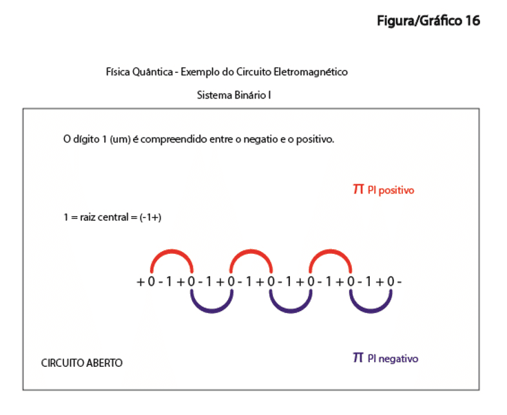
The Basic Logic Equation of the Binary System 1 is: + 0 – 1 + 0 – and / or 010 (Signal of – (minus) Equal to Negative and Signal of + (plus) Equal Positive. The digit 1 (ONE) is Negative and Positive because it is the Central Root and is not Neutralized.
Basic Logic Equation Binary System 2: – 0 – 1 – Ø + 1 + 0 + and/or 01Ø10 (Sign of – (minus) Equal to Negative, Sign of + (plus) Equal Positive, two Polarities respectively and the Ø (ZERO) of the Center = NEUTRAL) This is where one of the discoveries is. ZERO is Neutral, with Left side 1 (UM) Negative and Right side 1 (ONE) Positive. There Are Two 1 (UM) each with its specific polarity, comprised of 3 (ZEROS). There is 1 (ONE) Specific Positive and 1 (a) Specific Negative. Being the ZERO in the Center that is the Central Root Neutral.
In Binary System 1, the system works with only two Basic Physical elements, NEGATIVE and POSITIVE. In Binary System 2, the System works with 3 Basic elements of Physics the NEGATIVE, POSITIVE and NEUTRAL (The Neutral is the main element, and it does not have in the Binary System 1). Summarizing the NEUTRAL is one of the discoveries and where it becomes possible the programming for the BINARY SYSTEM 2 in Closed Code, so it gives if the name CODE CLOSED, because with the Neutral the Circuit is closed.
One More difference between the binary systems, is that in the Binary system 1 The CODE is OPEN and in Binary System 2 the CODE is CLOSED.
Why in Binary System 1 is the Code OPEN? It is an OPEN Source because there is no Neutral, being the Digit 1 (ONE) is open negative to the left and positive open to the right. The Digit 1 (a) is in the center and it is opened Positive and Negative. Digit 1 is the central root in Binary System 1. (Previously Stated in paragraph 003 and 004 and Exemplified in Graph 13 and Graph 16).
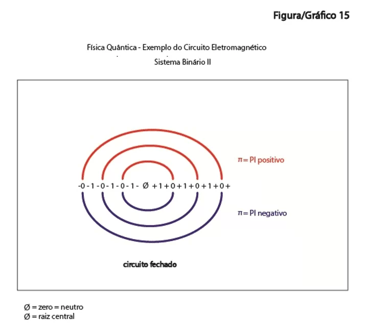
And the Binary System 2 is closed because the ZERO is the central root, it is Neutralized by the Digit 0 (ZERO) which is in the center, being the negative ends as much as the positive ones closed at 0 (ZERO) as well. There Are 3 ZEROS being one of them the center is the NEUTRAL. And There are two 1 (ONE), one (1) positive and the other 1 (ONE) Negative, understood between 3 (ZEROS) in the Basic Binary Equation. (Exemplified in paragraph 005 and Graph 12 and Graph 15).
Another technical difference is the logical, physical and mathematical equations between the two systems, while in the Binary System 1 the Root is squared ² √ (So the Pixel is Square) the Binary System 2 the Root is Cubic ³ √ (So the Pixel is Round). Remembering that 1 (UM) is equal to PI.
Equation Math Binary System 1 = π (² √ 0) – PI, Zero Square Root
Physical Equation Binary System 1 = + 0-π + 0-
Circuit Physical Logic System Binary 1 = (+-+-+-) Positive and Negative
Mathematical Equation System Binary 2 = 2 π (³ √ 0) – 2PI, Cubic Root of Zero
Physical Equation System Binary 2 =-0-π-Ø + π + 0 +
Logical Circuit Physics System Binary 2 = (— Ø+++) Negative, Neutral and Positive
In The basic circuit of the Binary System 1 is always: 1 (ONE) PI between 2 (TWO) ZEROS. And in the basic circuit of the Binary System 2 is: 2 (TWO) PI between 3 (THREE) ZEROS being the Zero Central equal to the Neutral.
And the Physical Logic is: In the Binary System 1 the 0 (ZERO) is negative and the 1 (ONE) is positive. Already in Binary System 2 O 0 (ZERO) is neutral and the 1 (ONE) is positive and the other 1 (ONE) Negative, and the 1 (ONE) Positive and another 1 (UM) Negative.
In Binary System 1, each Pixel that is square, it is arranged next to each other, side by side, one square next to the other. BINARY SYSTEM 1 = SQUARE PIXEL (See Graph 6, 7, 18 and 23).
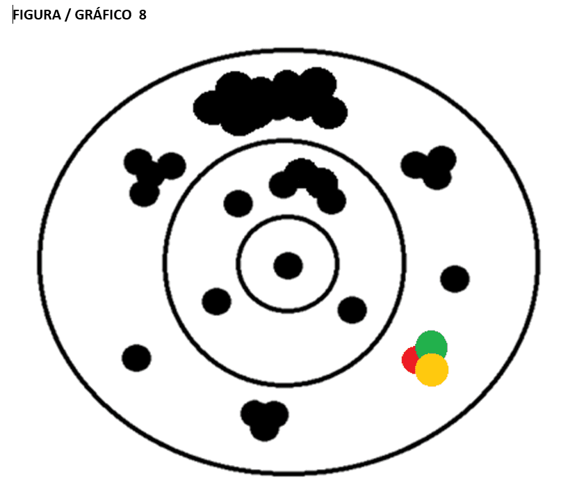
In Binary System 2, each Pixel that is Round/Spherical, is wrapped in a Circle within the other Circle, is a smaller Sphere, within another larger Sphere and so on. It is a Round pixel, a circle within the other, of different sizes, diameters and rays. Where a Round Pixel can be overlapped one over another, generating more image definition. BINARY SYSTEM 2 = ROUND/SPHERICAL PIXEL (See Graph 8, 19 and 24).
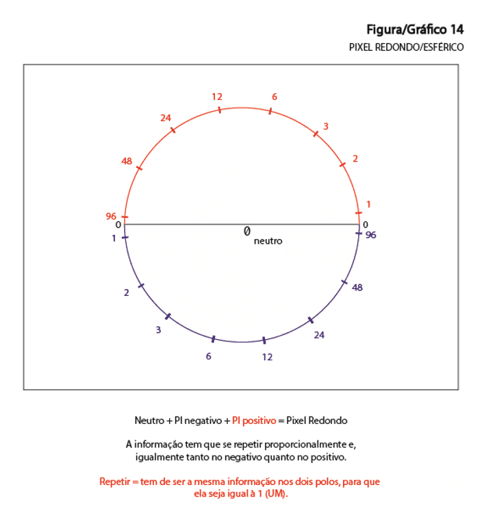
Physically Speaking at Pixel Redondo and or spherical, Being PI = 180º We have: NEUTRAL + PI NEGATIVE + PI POSITIVE = ROUND/SPHERICAL PIXEL and/or 0 (NEUTRAL ZERO) + 180º NEGATIVE + 180º POSITIVE = 360 º = ROUND/SPHERICAL PIXEL
4. BINARY SYSTEM 2 AND ITS ADVANTAGES
In the next few paragraphs I will cite technical differences between the Systems, such as energy savings, speed and security, improvements in which the Binary System 2 is superior to its predecessor.
In the Case of Energy Saving, an electronic device with the Binary System 2 with the Technology Current, can save between 10% a 15% On an electronic device such as tablets, mobile phones, notebooks, monitors and Smart TVs.
With the Technology Adapted, this means with Chips and Processors made for the Binary System 2, can save around 30% Power of electronic devices. Only with the change of the Binary System, which directly interferes in the processing of data from a device, making them much more agile, effective and economical. Imagine saving 30% Energy on a TV, on a Computer, even on a Smartphone, is a very high and considerable rate of economics. There Are 30% savings, this in all electronic devices, this would generate a great achievement of Sustainability for the Environment.
Speaking of Efficiency, The Binary System 2 is much more efficient than the Binary system 1, and a computer with the Binary System 2, with only one Processor, can be much faster than a Computer with Processing octa-core of the Binary System 1, thus being up to 8 times faster and more efficient. Near the best computer with Binary System 1 Nowadays, a device with Binary System 2 becomes a supercomputer.
Security, the Binary System 2 is not tested, but through its programming codes it can become a fully secure system counterattacks and threats from Hackers, your System would not allow intrusions and illegal accesses to the device data. Thus, the most secure programming, compilation and data storage platform exists.
Virus, on the platform of the Binary System 2, hardly the computer or the electronic device can be reached or damaged by a software Malicious Like Trojan horses among others that can even steal data like virus from Phishing, and by any other type of malicious software that may corrupt the internal system. By being Code Closed the Binary System 2 Virus-Free threats. Because even before the Virus tries to penetrate the System it is identified and its access to the device is denied.
A Critical point is that Binary system 1 becomes very vulnerable to Binary System 2, for the reason that Binary System 1 is Open Source and Binary System 2 is Closed Code. So, It’s very easy for Binary System 2 to invade Binary System 1 and decipher and break down the codes and encryptions that protect the Binary System 1. It’s impossible for anyone through a device in Binary System 1 to Be able to invade Binary System 2. The binary System 1 vulnerability to Binary System 2 can bring risks, which is why the transition between Binary Systems must be very Well done, so that no losses occur.
I Will talk about the problems that everyone has in Binary System 1, there occur several crashes, how many times you have not had to restart a program, or your computer or a device for the reason of operational crashes, this is connected directly to Binary System. Because the information in the System collide with each other, the information in the system moves squaring around them, causing crashes, loss of documents and files, and even hardware problems, causing a lot of damage Operating. Because It is square the system is easily corrupted generating huge losses, only because of the type of Binary System used. Already These problems and crashes will not be frequent or will not occur in Binary System 2 which is anti-Bug.
The consequence of a new Binary System is that all devices with the old Binary System will have to be replaced. The Binary System around the world will transition, that is, there will be a Binary System swap, because the Binary System 2 is better and safer and more efficient than its predecessor System.
The transition from the Systems is one of the main points of no loss and no losses in the Cybernetic world, and that at the time of the transition, people, companies and Governments around the world do not have the risk that their data and their safety are Violated and or corrupted.
Video – Games: It will be a revolution in the video games area, because it has a more powerful system and a new form of pixel composition and Programming, consoles (platforms) and games will reach another level of graphics becoming much more real, reaching extreme levels of virtual reality. You’ll Reach other levels of gameplay and your commands will reach and be much closer to reality.
Artificial Intelligence will reach new heights as never seen, will revolutionize all Technology Existing, new parameters and levels of virtual reality will be disseminated, a systemic evolution in all that the Binary System is employed. The Binary System 2 will spread a new Era in world computing and technology.
It is Only possible to program Binary System 2 using the Second Binary Sequential Code and/or Binary Logic Code 1 2 3 6 12 24 48 96. Remembering that Binary System 2 is a System of Processing, Programming and Data Storage. The Binary System II is a SYSTEM.
The BINARY SYSTEM 2 is in the process of patent registration.
The Binary System 2 was also decideed in PHI, which also follows the mathematical laws that through the Fibonacci Series measures, when analyzing the coefficient of two successive measures, is obtained the irrational number called (PHI), with the approximate value of 1.618. And this conjuncture of measures based on this number is called the Golden Ratio, or Áurea ratio, which is found, therefore, in the flowers, trees, waves, in the galaxies, shells, hurricanes, in the symmetrical face of the human being, in their joints Bone and the features of human beings, your heartbeat and your DNA. Also, in the refraction of light provided by the electrons of the atoms, in the vibrations, in other more manifestations And in the Binary System 2 that Works Basically with the Two Polarities, electromagnetic waves Positive and Negative and the Neutral. I Will perform mathematical demonstrations in addition to graphs explaining how the Fibonacci laws apply in Binary System 2.
5. EXPLANATION OF DEMONSTRATIONS, GRAPHS AND FIGURES
In the part of the drawings will be explained with formulas, mathematical demonstrations and graphs the differences between the systems, also demonstrate through differences between graphs, mathematical and physical calculations, try to explain in the best way possible, Knowing that this is a very complex subject the Binary System 2, of CODE name CLOSED.
In FIGURES Page 1, has the Mathematical Demonstrations 1, it is observed that every digit of 0.000000… 0001 to Infinity, when added until its last variable is sequential from 1 to 9 i.e. the sum of the digits of any number, being ZERO Neutral, added until its last variable is sequential from 1 to 9 Infinitely. As exemplified in Mathematical Demonstrations 1 We can understand in Graph 1 on Page 2, which is the Fibonacci Sequential, which explains why the sequential is from 1 to 9, we can see that the next quadrant is twice as many as the previous, as the example 2 is twice the [1], The 3 is double of the [1 and 2], the 4 is double of [1, 2 and 3], the 5 is twice as many as [1, 2, 3 and 4] and thus successively. And It is always sequential from 1 to 9, the 9 being twice as many of its predecessors, thus repeating the logic 1 2 3 4 5 6 7 8 9, 1 2 3 4 5 6 7 8 9, 1 2 3 4 5 6 7 8 9. Always the next one I type twice their predecessors.
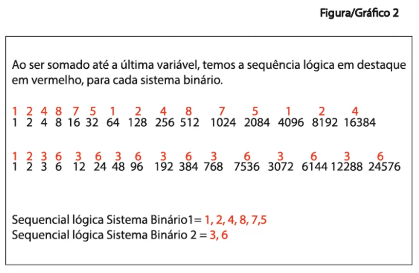
To explain the Chart 2 and the Mathematical Demonstrations 2 and 3. That by following the mathematical rule that any number added up to the last variable is sequential from 1 to 9, explained in Mathematical Statements 1, we obtain the following Logical Sequential for the Binary System 1 – 1, 2, 4, 8, 16, 32, 64, 128 = 1, 2 , 4, 8, 7, 5, 1, 2. The logic that repeats is these 6 Digits – 1 2 4 8 7 5. In Binary System 2 we obtain the following Logical Sequential – 1, 2, 3, 6, 12, 24, 48, 96 = 1, 2, 3, 6, 3, 6, 3, 6. Being that the repeating logic is just these 2 Digits, 3 and 6 continuously and infinitely. Summarizing the Binary System 2 is possible to go to infinity following logic 3 and 6, which is related to the propagation of electromagnetic waves exemplified in Graph 12.
Figure/Graph 2, when analyzing the Binary System Logical Sequential 1 We see that it is a larger and more complex sequence than the Binary system 2, while one repeats the 6-digit sequence – 1, 2, 4, 8, 7, 5 which is the case of Binary System 1. In Binary System 2, a sequence of only 2 digits is repeated – 3 and 6 respectively and continuously, this is due to the case that the System Work evenly in both polarities and neutralized, which I will explain better in Graph 12.
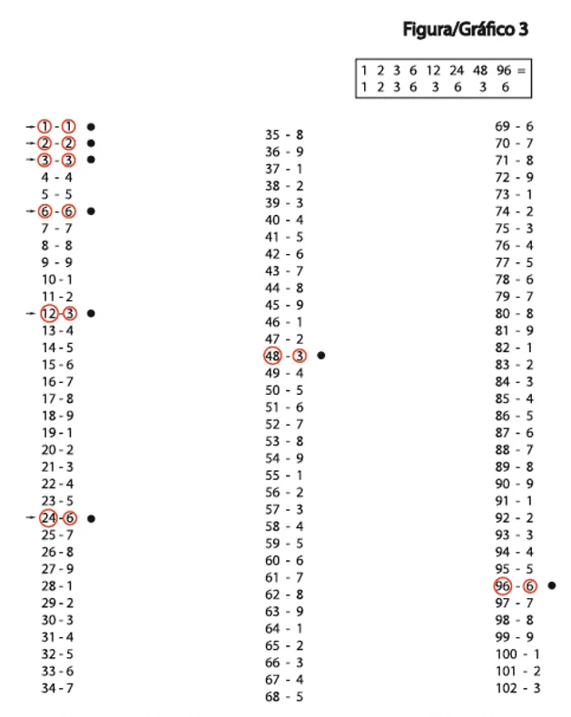
Figure/Graph 3 serves to explain that the logical sequential of Binary System 2 which is 3 and 06.
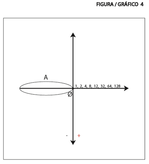
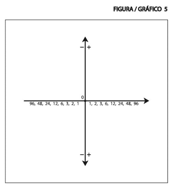
Figure/Graph 4 and 5 show the difference between systems when exposed to X and Y Axes. Graph 4 is Binary System 1 and Graph 5 is Binary System 2. We Can see that in Binary System 2 The logic contemplates every graph, already in the Binary System 1 only half.
Figure/Graph 6 and 7 is a demonstration of how the approximate square pixel on a computer monitor is, is an image definition. A square Pixel next to another square Pixel.
The Figure/Chart 8 Demonstrations As is the disposition of the Round Pixels, one ball inside the other that can be overlapped one over the other. One Pixel round on top of the other round Pixel. This pixel May be larger or smaller, depending on the availability of the system.
Figure/Graph 9 – MATHEMATICAL STATEMENTS 4 is exemplified by how the Reading Binary system is a demonstration of how the Systems are Programmed, is a comparison of how the binary reading in the Binary System 1 and how is the binary reading in the Binary System 2. Summarizing is how the system is written in a binary way. We Can verify that one System is written differently from the other.
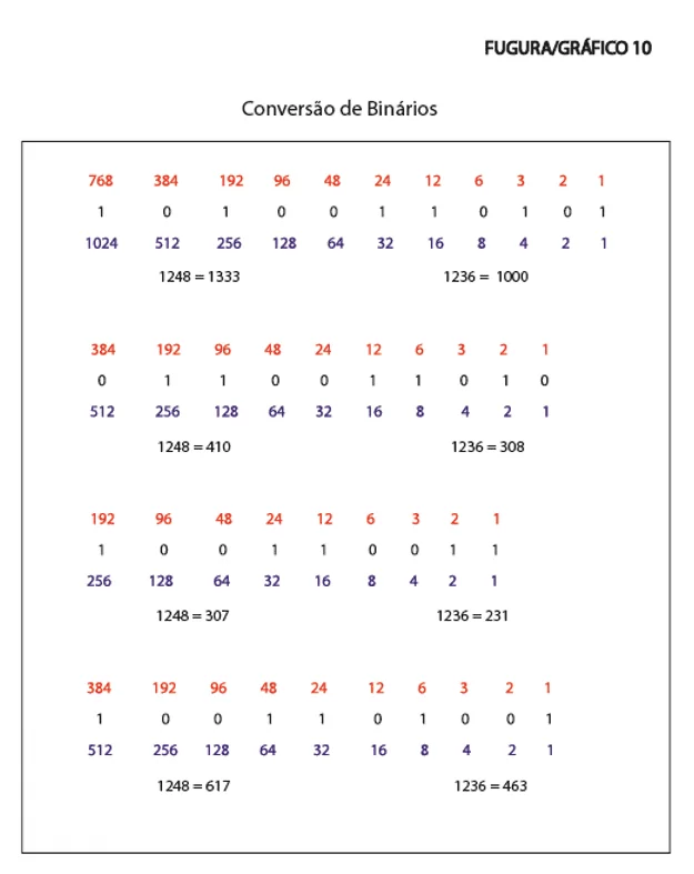
Figure/Graph 10 is called Binary Conversion I will try to explain and describe this picture in the smallest detail for a better understanding. CONVERSION OF binaries, we can see the differences between binary Systems 1 and Binary System 2 in the reading of Binary Codes, In Example 1 (10100110101) While the Binary System 1 described by the code 1248 converts the data arranged in the number 1333, in Binary System 2 that is described by the code 1236 converts the same logical sequence of data arranged in 1000. So, the two systems read the same binary sequence, but the Binary System 1 reads at 1333 and the Binary System 2 reads in 1000. As exemplified in Figure 10. What this means is that the Binary System 2 reads the same sequence before the Binary System 1, He reads First, this can also mean that it reads the same code and or sequence faster, it is faster than the Binary System 1. And that can also store a larger data capacity in the same sequence. To convert the data into binaries, in each system type 1248 or 1236, simply add where the digit 1 appears, that the result is the number you are willing to have. (If there is any doubt as to how binary conversion is done, there are videos on the internet YouTube How the conversion is done). We Can see in all the examples below that Binary System 2 reads the same logical sequences first as the Binary System 1, in Example 2 (0110011010), in system 1248 = 410, while and in system 1236 = 308. In Example 3 (100110011), in system 1248 = 307, while in system 1236 = 231. In Example 4 (1001101001), in system 1248 = 617, while in system 1236 = 463. It Is a high difference that can directly imply the speed and volume of data processing as much as energy savings in the process.
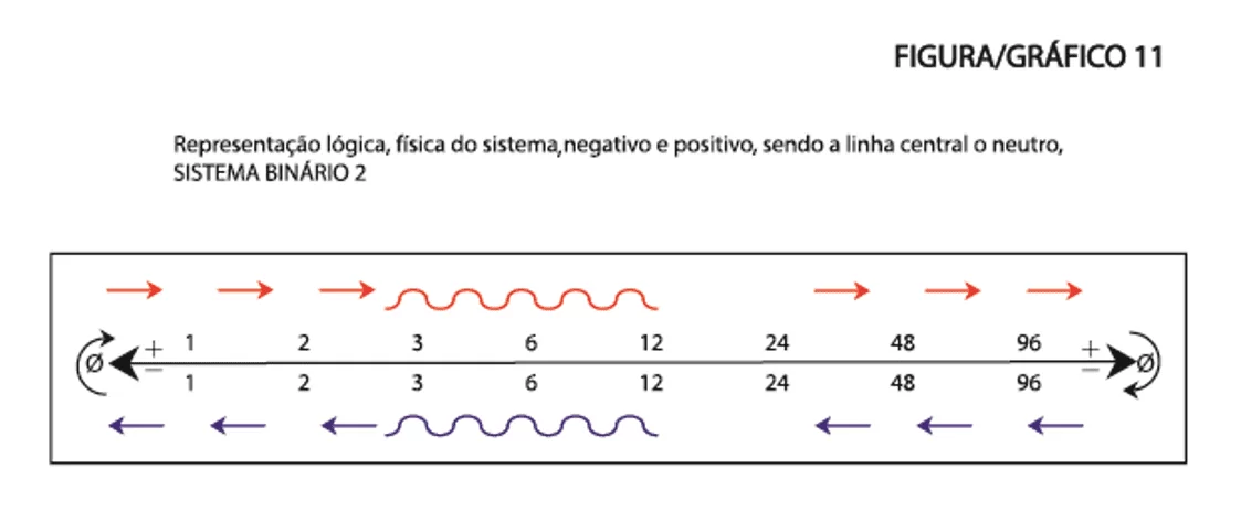
Figure/Graph 11 is the physical logical representation of the system in negative and positive, being the line in the middle the neutral, BINARY SYSTEM 2. It is a demonstration of the Physical Circuit of the Binary System 2.
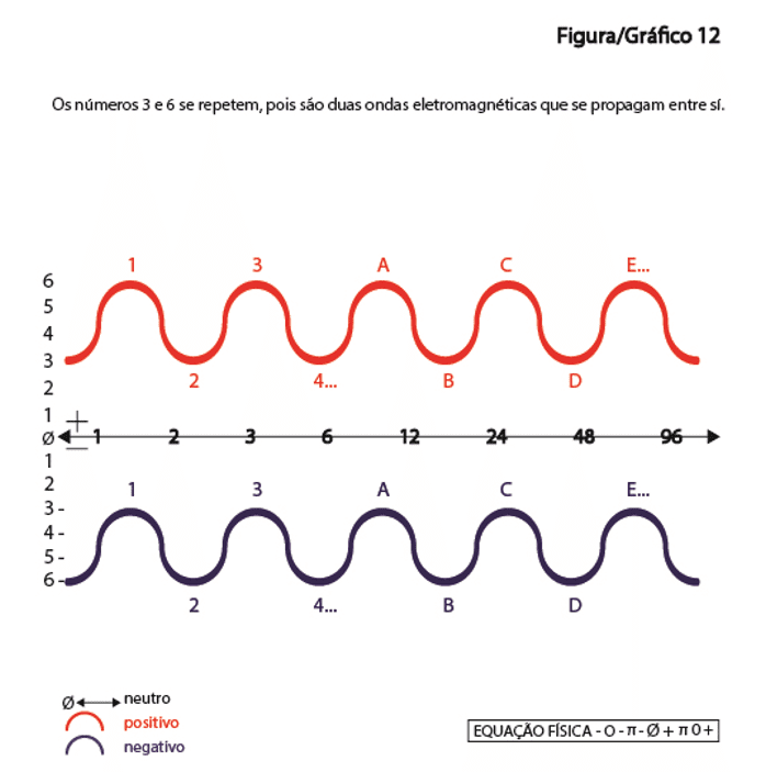
Figure/Graph 12 explains the Binary System 2 that are TWO electromagnetic Waves, one Positive Electromagnetic Wave and another Negative Electromagnetic Wave that propagate among themselves, which follows the logic 3,6,3,6,3,6, continuously and infinitely, I will read the graph and explain the meaning of the two electromagnetic waves that propagate in 3 and 6. While in the electromagnetic wave Positive The Wave Crest is in 6, in the electromagnetic wave Negative The Wave Crest is at the 3, and subsequently when in the electromagnetic wave Positive The Wave Crest is at 3, in the electromagnetic wave Negative the Wave Crest is In 6 and so on, so the logical sequence 3,6,3,6,3,6. While One wave is 3 the other is 6 and when one wave is 6 the other is 3. The Two waves are symmetrical they propagate each other in opposite directions one negative and one positive, one Sense From left to right and another wave clockwise from right to left. In 3 and 6, and in 2 PI. PI is the length of a wave as previously stated, there is PI Negative and PI Positive, the System is programmed in PI.
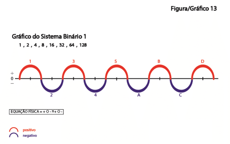
Figure/Graph 13 explains the graphical logic of Binary System 1, compared to Graph 12 of Binary System 2. In Binary System 1 is only AN Electromagnetic Wave that spreads between the Positive and the Negative and/or 1 PI that spreads between the positive and the negative.
Figure/Graph 14 shows that the PI POSITIVE + PI NEGATIVE + NETRO = 360 º ROUND/SPHERICAL PIXEL. The information has to be repeated both in the negative and in the positive, we have to program 1 2 3 6 12 24 48 96 NEGATIVE and 1 2 3 6 12 24 48 96 POSITIVES. The same information in both polos and both Neutralized by Neutral at the Center.
Figure/Graph 15 is an example of the Electromagnetic Circuit of the Binary System 2.
Figure/Graph 16 is an example of the Electromagnetic Circuit of the Binary System 1. Graphics 15 and 16 are a comparison between each other.
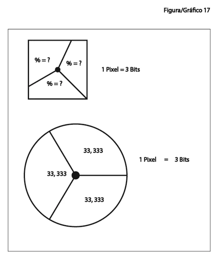
Figure/Graph 17 is the difference between the 3 Bits in the Square Pixel and the Round Pixel, in Binary System 1 which is Pixel square the Bits are not symmetric or proportional, are not evenly distributed because it is a square, each Bit varies its percentage. In Binary System 2, the Pixel is round the percentage of Bits are distributed equally and proportionally, being 33.333% for each Bit as the Graph reveals.
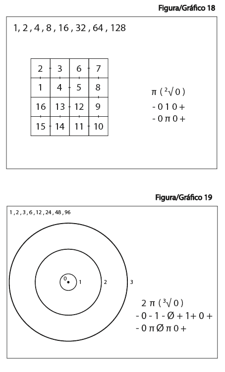
Figure/Graph 18 is the graphical layout of the Binary System Pixels 1 and the equations referring to System 1 2 4 8 16 32 64 128.
Figure/Graph 19 is the graphical layout of the Binary System 2 Pixels and the equations referring to System 1 2 3 6 12 24 48 96. Charts 18 and 19 are a comparison between each other.
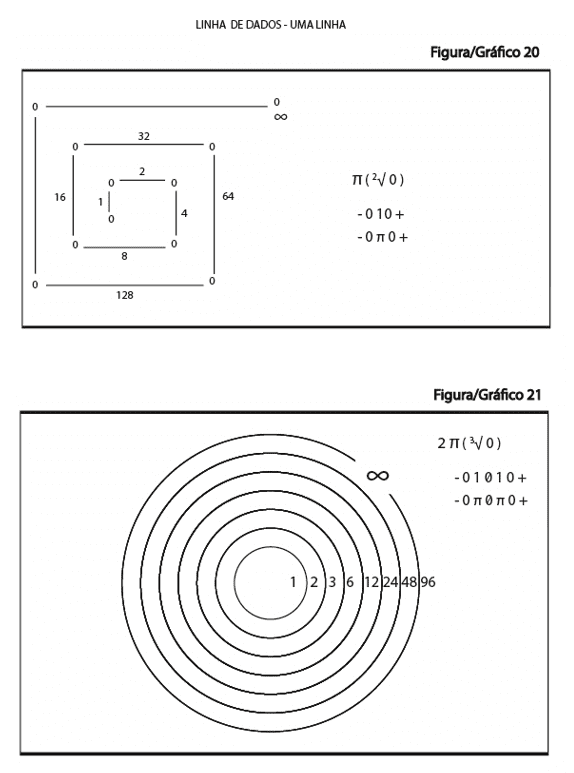
Figure/Graph 20 demonstrates how reading is in a data row in Binary System 1. That’s Square.
Figure/Graph 21 demonstrates how to read in a row of data the characteristics of the Binary System 2. Which is round. Charts 20 and 21 are also a comparison between each other.
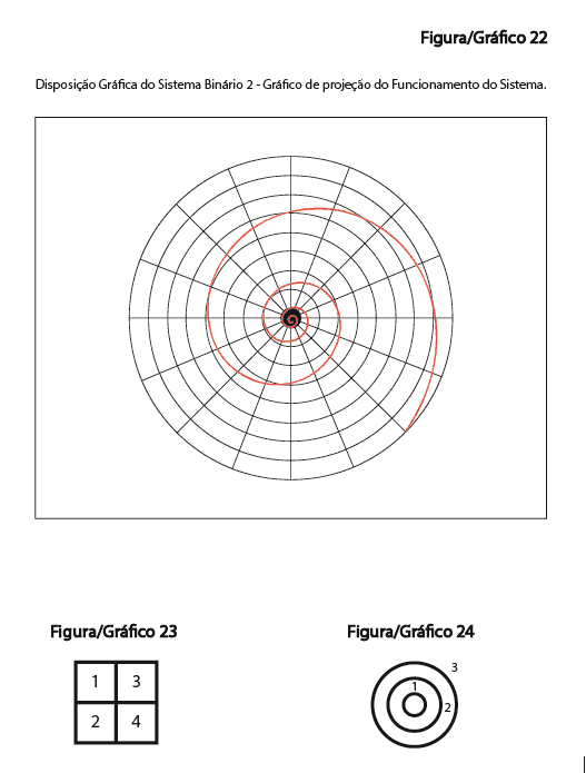
Figure/Graph 22 is a demonstration of the graphical layout of the Binary System 2, is the Result Graphical programming, how would be the raw operating form of the provision of system information for example.
Figure/Graph 23 is a basic graphical way to express Square Pixels.
Figure/Graph 24 is a basic graphical way to express Round Pixels.
The Binary System 2 is a new data processing technology geared to any type of electronic electro, the Binary System 2 comes to improve and optimize computing across the planet, will be a new digital Age in the world, not counting all Technological advantages in all senses, in relation to the technology of everything in which the system can be employed. Thus, new technologies will be generated from this new technology.
6. Demonstrations, GRAPHS and figures
1/22
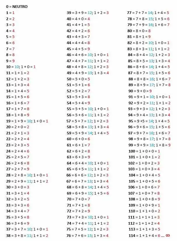
MATHEMATICAL DEMONSTRATIONS 1
Every digit of 0.000000… 0001 to Infinity, when summed up to its last variable is sequential from 1 to 9 i.e. the sum of the digits of any number, being ZERO Neutral, is sequential from 1 to 9 Infinitely. As exemplified below:
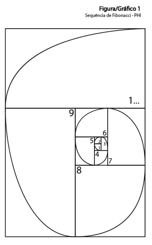
2/22
Sequential Fibonacci (PHI) explains why the sequence is from 1 to 9, below we can see that the next quadrant is double all the previous, as example the 2 is twice the [1], the 3 is twice the [1 and 2], the 4 is twice the [1 , 2 and 3], the 5 is twice as many as [1, 2, 3, and 4] and thus successively. And It is always sequential from 1 to 9, the 9 being twice as many of its predecessors, thus repeating the logic 1 2 3 4 5 6 7 8 9, 1 2 3 4 5 6 7 8 9, 1 2 3 4 5 6 7 8 9. Always the next one I type twice their predecessors.
3/22
4/22
MATHEMATICAL DEMONSTRATIONS 2
1 BINARY SYSTEM – Adding to the last variable contains the following logical sequence.
1 2 4 8 16 32 64 128 …
1 = 1
2 = 2
4 = 4
8 = 8
16 = 1 + 6 = 7
32 = 3 + 2 = 5
64 = 6 + 4 = 10; 1 + 0 = 1
128 = 1 + 2 + 8 = 11; 1 + 1 = 2
256 = 2 + 5 + 6 = 13; 1 + 3 = 4
512 = 5 + 1 + 2 = 8
1.024 = 1 + 0 + 2 + 4 = 7
2.048 = 2 + 0 + 4 + 8 = 14; 1 + 4 = 5
4.096 = 4 + 0 + 9 + 6 = 19; 1 + 9 = 10; 1 + 0 = 1
8.192 = 8 + 1 + 9 + 2 = 20; 2 + 0 = 2
16.384 = 1 + 6 + 3 + 8 + 4 = 22; 2 + 2 = 4
32.768 = 3 + 2 + 7 + 6 + 8 = 26; 2 + 6 = 8
65.536 = 6 + 5 + 5 + 3 + 6 = 25; 2 + 5 = 7
131.072 = 1 + 3 + 1 +0 + 7 + 2 = 14; 1 + 4 = 5
262.144 = 2 + 6 + 2 + 1 + 4 + 4 = 19; 1 + 9 = 10; 1 + 0 = 1
524.288 = 5 + 2 + 4 + 2 + 8 + 8 = 29; 2 + 9 = 11; 1 + 1 = 2
1.048.576 = 1 + 0 + 4 + 8 + 5 + 7 + 6 = 31; 3 + 1 = 4
2.097.152 = 2 + 0 + 9 + 7 + 1 + 5 + 2 = 26; 2 + 6 = 8
4.194.304 = 4 + 1 + 9 + 4 + 3 + 0 + 4 = 25; 2 + 5 = 7
8.388.608 = 8 + 3 + 8 + 8 + 6 + 0 + 8 = 41; 4 + 1 = 5
MATHEMATICAL LOGIC, SEQUENTIAL LOGICAL BINARY SYSTEM 1 = 1, 2, 4 , 8, 7, 5.
5/22
MATHEMATICAL DEMONSTRATIONS 3
BINARY SYSTEM 2 – Summing up to the last variable Contains The following logical sequence.
1 2 3 6 12 24 48 96 …
1 = 1
2 = 2
3 = 3
6 = 6
12 = 1 + 2 = 3
24 = 2 + 4 = 6
48 = 4 + 8 = 12; 1 + 2 = 3
96 = 9 + 6 = 15; 1 + 5 = 6
192 = 1 + 9 + 2 = 12; 1 + 2 = 3
384 = 3 + 8 + 4 = 15; 1 + 5 = 6
768 = 7 + 6 + 8 = 21; 2 + 1 = 3
1.536 = 1 + 5 + 3 + 6 = 15; 1 + 5 = 6
3.072 = 3 + 0 + 7 + 2 = 12; 1 + 2 = 3
6.144 = 6 + 1 + 4 + 4 = 15; 1 + 5 = 6
12.288 = 1 + 2 + 2 + 8 + 8 = 21; 2 + 1 = 3
24.576 = 2 + 4 + 5 + 7 + 6 = 24; 2 + 4 = 6
49.152 = 4 + 9 + 1 + 5 + 2 = 21; 2 + 1 = 3
98.304 = 9 + 8 + 3 + 0 + 4 = 24; 2 + 4 = 6
196.608 = 1 + 9 + 6 + 6 + 0 + 8 = 30; 3 + 0 = 3
393.216 = 3 + 9 + 3 + 2 + 1 + 6 = 24; 2 + 4 = 6
786.432 = 7 + 8 + 6 + 4 + 3 + 2 = 30; 3 + 0 = 3
1.572.864 = 1 + 5 + 7 + 2 + 8 + 6 + 4 = 33; 3 + 3 = 6
3.145.728 = 3 + 1 + 4 + 5 + 7 + 2 + 8 = 30; 3 + 0 = 3
6.291.456 = 6 + 2 + 9 + 1 + 4 + 5 + 6 = 33; 3 + 3 = 6
MATHEMATICAL LOGIC, SEQUENTIAL LOGICAL SYSTEM BINARY 2 = 3, 6
6/22
7/22
GRAPH X and Y AXIS OF the BINARY SYSTEM 1.
A = NEGATIVE OPEN
8/22
GRAPH X and Y AXIS OF the BINARY SYSTEM 2.
9/22
THE IMAGES BELOW SHOW THE SQUARE PIXELS SIDE BY SIDE
FIGURE/GRAPH 6
FIGURE/GRAPH 7
10/22
IN A ROUND PIXEL PIXEL INSIDE THE OTHER, AND YOU CAN SUPERIMPOSE A PIXEL ON TOP OF ANOTHER PIXEL. GENERATING MORE GRAPHICS AND IMAGE DEFINITION.
EXAMPLE:
11/22
MATHEMATICAL DEMONSTRATIONS 4 – FIGURE/GRAPH 9
BINARY
In This table below is a demonstration of how the systems are programmed, is a comparison of how the binary reading in the Binary System 1 and how is the binary reading in the Binary System 2.
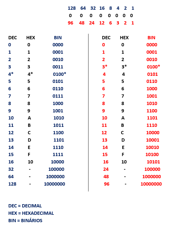
In Binary System 1 closes 100 of a Square Nucleus in the 4.
In Binary System 2 It closes 100% of a Round/Spherical Nucleus in 3.
12/22
13/22
14/22
15/22
16/22
17/22
18/22
19/22
20/22
21/22
22/22
7. SUMMARY
“CLOSED CODE” To Register the BINARY SYSTEM 2 of the CLOSED CODE name, it is only necessary to make use of the Binary Sequential Code – 1 2 3 6 12 24 48 96 and its subsequent values 192 384 768 1536 3072 6144 12288 24576 and so on.
“CLOSED CODE” Only becomes possible to program Binary System 2 using the Second Binary Sequential Code 1 2 3 6 12 24 48 96. Remembering that I did the patent registration of the Binary System II. The Binary System II is a System.
“CLOSED CODE” high quantum calculations Were performed to achieve and ensure this discovery on the Binary System 2. Deciphering the Binary System 2 required advanced knowledge in Mathematics, Logic, Trigonometry, Biology, Physics and Quantum Physics.
“CLOSED CODE” The System has not yet been tested or homologated, and it is still necessary to be Destrinchado, studied and performed all types of tests before its implementation and introduction in the market. This is a very sensitive new programming, especially because it is in its early stages. Where only scientific discoveries were made through mathematical, logical, physical and quantum studies.
“CLOSED CODE” We Know that the binary sequence 0 (ZERO) and 1 (ONE) is negative and positive respectively. We also Know that the 0 (ZERO) in physics is neutral. Just position the ZERO in Binary logic 1 2 3 6 12 24 48 96 in a logical way so that it functions as Neutral in the Binary Sequence.
“CLOSED CODE” The Binary System 2 is a new data processing technology geared to any type of electronic electro, the Binary System 2 comes to improve and optimize computing across the planet, will be a new digital Age on the planet , without relying on all the technological advantages in every way, in relation to everything in which the system can be employed. New technologies will be generated from this new technology.
“CODE CLOSED” I will make available a Technical Summary with the differences between BINARY SYSTEMS 1 and BINARY SYSTEMS 2 for a better understanding of the Descriptive Report.
8. TECHNICAL SUMMARY
Programming for the Binary System 2.
Name: “Closed Source”
Cause:
Binary System 2
Effect:
Pixel Round/Pixel Spherical
Binary Sequential and/or Sequential Binary Code:
* 1 2 3 6 12 24 48 96 *
Technical Differences between Binary System I and Binary System II:
Binary System I – Pixel Square
Binary Code: 1 2 4 8 16 32 64 128 – Open Source
Logical Sequential: 1.2, 4, 8, 7, 5.
Central Root: 1 (ONE)
Binary Basic Logic Equation 1: + 0 – 1 + 0 – and/or 010 (Minus Sign) Equals Negative, + Sign (plus) Equals Positive. Polarity Difference)
Mathematical Equation: π (² √ 0) PI, Zero Square Root
Physical Equation: + 0-π + 0-
Physical Logic Circuit: (+-+-+-) Positive, Negative, Positive, negative, successively.
Binary System II – Pixel Round
Binary Code: 1 2 3 6 12 24 48 96 – Closed Code
Logical Sequential: 3.6
Central Root: 0 (ZERO)
Binary Basic Logic Equation 2: – 0 – 1 – Ø + 1 + 0 + and/or 01Ø10 (minus) Equal to Negative, + Sign (plus) Equal Positive, The two Polarities respectively and the Ø (ZERO) of the Center = NEUTRAL)
Mathematical Equation: 2 π (³ √ 0) – Two PI, Zero Cubic Root
Physical Equation: -0-π-Ø + π + 0 +
Physical Logic Circuit: (—Ø+ + +) Negative, Neutral and Positive.
Zero Equal to Neutral and ONE Equal to PI.
The Main technical difference is that in the Binary System I the central root is the 1 (ONE) and in the Binary System II the central root is 0 (ZERO).
Physical Logic is: In the Binary System 1 The 0 (ZERO) is negative and the 1 (ONE) is positive. Already in Binary System 2 the 0 (ZERO) is neutral and the 1 (ONE) is positive and another 1 (ONE) is negative That is 1 (ONE) Positive and another 1 (ONE) Negative.
Description:
Binary System 2, this is a new computer (Generation 2), is a new system for compiling, processing, programming and storing data.
It is only possible to program Binary System 2 using the Second Logical Sequential Code and/or Binary Sequential Code 1 2 3 6 12 24 48 96. We Know that the binary sequence 0 (ZERO) and 1 (ONE) is negative and positive respectively. We also Know that the 0 (ZERO) in physics is neutral. Just position the ZERO in Binary logic 1 2 3 6 12 24 48 96 in a logical way so that it functions as Neutral in the Binary Sequence.
Which is the operating form of the system that was registered in Patent. Remembering that the Binary System 2 a System Programming and Data Storage. The Binary System II is a System.
Purpose:
Binary System 2 – CLOSED CODE – BINARY CODE: * 1 2 3 6 12 24 48 96 * and their subsequent values 192 384 768 1536 3072 6144 12288 24576 and etc.
Summary:
The Binary System 2 is a new data processing technology geared to any type of electronic electro, the Binary System 2 comes to improve and optimize computing across the planet, will be a new digital Age on the planet, not relying on all Technological advantages in every way, in relation to everything in which the system can be employed.
REFERENCES
Binary System
https://pt.wikipedia.org/wiki/Sistema_de_numera%C3%A7%C3%A3o_bin%C3%A1rio
Pixel
https://pt.wikipedia.org/wiki/Pixel
Fibonacci sequence
http://pegasus.portal.nom.br/proporcao-aurea-e-sequencia-de-fibonacci/
[1] Bachelor’s Degree in Business Administration with Qualification in Foreign Trade, Graduate from University Paulista UNIP, Economist.
Submitted: Sep, 2018.
Approved: February, 2019.