REVIEW ARTICLE
MENEGHIN, Pedro Henrique [1], LOPES, Cintia Abdelnur [2]
MENEGHIN, Pedro Henrique. LOPES, Cintia Abdelnur. Mechanical projects: dimensioning of shafts with correction for keyway and bearing support. Revista Científica Multidisciplinar Núcleo do Conhecimento. Year. 07, Ed. 05, Vol. 06, pp. 56-76. May 2022. ISSN: 2448-0959, Access link: https://www.nucleodoconhecimento.com.br/engineering-mechanical-engineering/mechanical-projects, DOI: 10.32749/nucleodoconhecimento.com.br/engineering-mechanical-engineering/mechanical-projects
ABSTRACT
This article goes through several steps in order to deliver a reliable result, according to the ASME method, of a shaft dimensioning, aiming to automate the calculation memorial process for shaft projects. The design steps are: stress diagrams, fatigue and geometry analysis (if necessary); correction due to discontinuity (if any); shaft diameter correction due to keyway (if any); and correction due to manufacturer’s selected bearing support (adopting SKF models). In this way, the article aims, in order to comply with the literature and standards, to dimension transmission shafts. The results of the exercises solved in the book Projeto de Máquinas: Uma abordagem integrada will be used as a reference. The developed program aims to meet both professional and academic demands by optimizing the calculations to obtain the diameter of a shaft. In addition, the project is justified by the fact that it allows several changes for a better understanding, either for a designer or for a student. The software used to automate the processes and obtain the results will be Mathcad Prime 5.0 from PTC Enterprise. At the end of the article, along with the results and conclusion, there are examples of design problems solved by the program, along with their explanations and comparisons with the results obtained in the Norton’s book.
Keywords: Automation, Shaft dimensioning, Machine design.
1. INTRODUCTION
Norton (2013) states that transmission shafts are extremely important components in basically all parts of rotating machinery, since they transmit rotation and torque from one location to another (one part to another). In this way, a machine equipment designer is always in touch with the arduous task of dimensioning shafts.
Niemann (1971) still defines that the axes only serve to support machine parts, fixed, mobile or oscillating and states that the axes are requested to torsion, or torsion and flexion.
The fundamental kinematic constructs of our mechanical universe are the wheel and axle. An essential piece of this joint of revolution is the shaft, as it constitutes a good example of a quasi-static and dynamic loaded body. (SHIGLEY; MISCHKE; BUDYNAS, 2005).
With these assumptions, the article consists of building a program capable of providing the value of an axis, through pre-established information, having varied flexion and torsion due to torque.
As Hibbeler (2010) states about the performance of axes and their requests:
O resultado é que muitas vezes estarão sujeitos à tensão cíclica ou de fadiga, causadas pelas cargas combinadas de flexão e torção que devem transmitir, ou às quais devem resistir. Além dessas cargas, podem existir concentrações de tensão em um eixo devido a chavetas, acoplamentos e transições repentinas em sua área de seção transversal. Portanto, para projetar um eixo de forma adequada, é necessário levar em conta todos esses efeitos.
Analyzing the paragraph above, there is a need to make corrections in the dimensioning of the shaft. For such calculation, the values found in the first moment, which are the alternating and average components of the Bending Moment and Torque, will serve to make the necessary corrections. The axis will then go through two stages of correction: resistance (fatigue) and geometric.
At this stage, analyzes will be performed via Excel to help minimize errors in the diameter found. After that, the corrected value will be rounded according to manufacturing compliance.
With that, the program will correct the diameter found so that it can be used with keyway and bearing supports. The type of keyway established in the program is parallel to the axis. Furthermore, if there is a discontinuity in the shaft, it will be recalculated due to stress concentrations, generated by the creation of the milled seat in the shaft body.
Then, recalculate the diameter if the shaft is coupled to one or more bearing supports, both of which are rolling element bearings.
All calculated axes will be checked with a safety factor that will be established by the user.
According to the authors Ferreira; Campos and Dias (2017) about the use of software in a student environment:
Existe a possibilidade da aprendizagem individualizada ser favorecida com o uso desse recurso tecnológico, já que ele só executa o que lhe é mandado, limitando-se ao potencial do usuário. O que permite ao professor ter uma visão clara de qual a limitação do seu aluno, e assim poder ajudá-lo de uma forma mais precisa. Sem contar que o educando ganha autonomia na hora de realizar seus trabalhos. Além da aprendizagem individualizada as salas informatizadas também facilitam a aprendizagem em grupo, pois os ambientes se tornam mais dinâmicos, as atividades são desenvolvidas com menos imposição, os alunos perdem o medo de errar, eles se auto-ajudam na realização das tarefas, e isso tudo favorece a uma nova socialização.
From these observations, the relevance of the article is to be able to help in the classroom, as in the subjects of Mechanics of Solids, Machine Elements and Machine Design, since the class itself becomes more visual. Thus, as they are disciplines that require a lot of calculations and end up becoming exhausting, the software will help in the dynamics of the class, as mentioned in the paragraph above.
It can also be used as a tool to design real axes, since the calculation methodology used is not merely theoretical, making use of the ASME method.
Pinheiro et al. (2014) state that due to the large number of equations and the interconnection of factors between the calculations, it is of fundamental importance to use calculation software to optimize the design time. And, with these software, they also provide a faster comparison if it is necessary to change some parameter for a desired axis. In short, the program aims to facilitate and optimize the design time of shafts in its various applications.
Currently many software can be used to assist in the sizing steps. For example, it is possible to obtain the bending moment diagrams from the FTOOL software, while the calculation routines can be created using software such as MATLAB, MATHCAD or EES. (PINHEIRO; NOGUEIRA; COSTA, 2014).
Therefore, the article has the general objective: to create a program that acts as a calculation routine in Mathcad to design axes.
The specific objectives are: to obtain the shaft diameter with fatigue safety factors.
Fatigue is a change in the structure of a mechanical element that happens in a localized, progressive and permanent way. Occurs when elements are subject to variable stresses, caused by dynamic loading. (SOUSA, 2011).
a) Correct the shaft diameter for the geometric factor.
The possible failures that the power transmission shaft may have, according to Collins (2006) are: due to fatigue; failure due to force-induced elastic deformation (resistance); and wear failure (geometric).
b) Correct the previous diameter if there is a discontinuity in the shaft.
According to Norton (2013), in some cases the design of an axis can be carried out without any variations in its section, but it is more usual to need shoulders or steps. This is because, in different dimensions, the shaft needs to be adapted for fixed elements, such as the bearing supports that will be discussed here in the developed program.
This way, if the shaft to be designed needs to have more than one diameter, the program will make the necessary correction with the shaft showing two sizing values.
c) Obtain the corrected diameter by creating a slot due to the use of a parallel keyway on the shaft, if any, with its acceptable safety factors: shearing and crushing.
According to Juvinall and Marshek (2008) the keyway is one of the most common connections between a shaft and a transmission hub.
Juvinall and Marshek (2008) also state that, when a shaft diameter is designed based on resistance, the keyway must be included in the calculations, since, with this keyway, there is also a stress concentration generated.
Norton (2013) says, about the type of keyway that will be used for dimensioning, that the parallel keyway have their particular sizes of the cross sections and the depth of the seats, or slots, standardized by ANSI and ISO.
d) Obtain the corrected diameter to be coupled to a rolling element bearing support: spherical or cylindrical.
According to Norton (2013), the rolling elements bearing supports can be used to allow low friction. They are typically chosen from manufacturers’ catalogs in order to accommodate the loads pertaining to a given project. In addition, such bearing supports can withstand radial, axial loads or even a combination of both, depending on the design.
The focus of the developed software will be in relation to shaft designs, and therefore will not have depth in bearing supports designs that will be used only as correction factors for shaft diameters.
e) Provide the actual values of the shaft diameter(s) and their specifications when requested.
2. MATERIAL AND METHOD
The main material used will be Norton’s work, Projeto de Máquinas: Uma abordagem integrada, 4th ed., 2013. This work was chosen since it proposes an easy-to-understand logical sequence for the calculations that will be performed. With such material and scripts prepared during the course in the Machine Element classes, the method used for the calculations will be through the MathCad Prime 5.0 software from PTC Enterprise. Such software has a programming logic equivalent to the C language.
The software in question will have the help of Excel for the formation of graphs, with the data obtained in Norton’s work, to make the necessary adjustments to add more efficient data to the project. To compare values, the Wolfram Alpha website will be used (a site intended to present mathematical solutions, from simple polynomials to complex integrations), since it presented the same answers found in the work cited in the previous paragraph.
The program developed for dimensioning shafts will have an if, else and for programming format. This guarantees more accurate, faster results and so that calculations are automated every time a factor needs to be changed.
The if-else statement is one of the C language flow control statements. It allows you to indicate the circumstances under which a given statement or set of statements should be executed. (DAMAS, 2007).
Damas (2007) also explains that such an instruction works as a “true or false”. If the established condition (if) is true, it executes the first statement and, if false, executes the second (else).
The for statement (or for loop, as it is commonly known), is particularly suited to situations where the number of iterations is known a priori. (DAMAS, 2007).
So, as Damas (2007) explains, the for statement is an iterative method used when it is known how many times or even when a given value must be iterated to arrive at an admissible value.
Thus, the program will allow the automation of calculations for dimensioning axes, even with specific conditions for certain equations.
3. RESULTS
The results will be presented as follows: first, the exercises from the book Projeto de Máquinas: Uma abordagem integrada (NORTON, 2013), highlighting the input data. After each problem, the results obtained by the project software. The necessary explanations are found together with the development of the results.
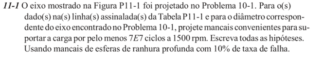
3.1 PROJECT PROBLEM 1
The following exercise demonstrates a design for a uniform shaft, biased, with varying torque and with a load applied after its last reference support.
Figure 1 – Problem 1
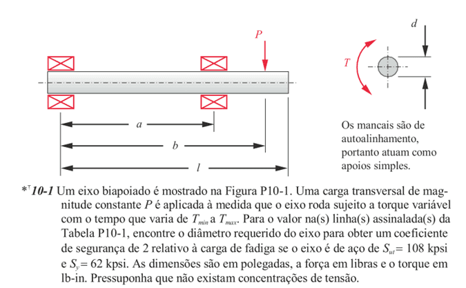
Table 1 – Values for the year
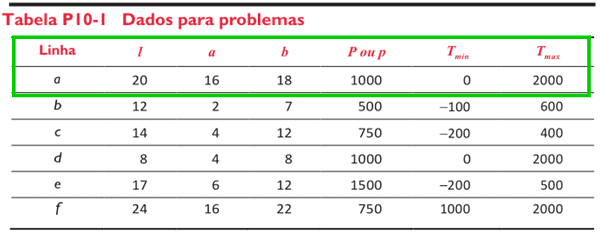
Table 1 has the data for solving the exercise. The line in green presents the ones that will be used to compare the answers in the book with the one obtained by the project in question.
Figure 2 – Answer to the first exercise

Above, in Figure 2, it is observed that the result of the shaft diameter is equal to 1.188 inches.
Below, there is an image of the project’s initial page, in which the user needs to inform the data values presented in Table 1. It is possible to notice that, to facilitate understanding, there are explanations in the software for its correct use.
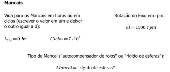
Figure 3 – Table data for the project
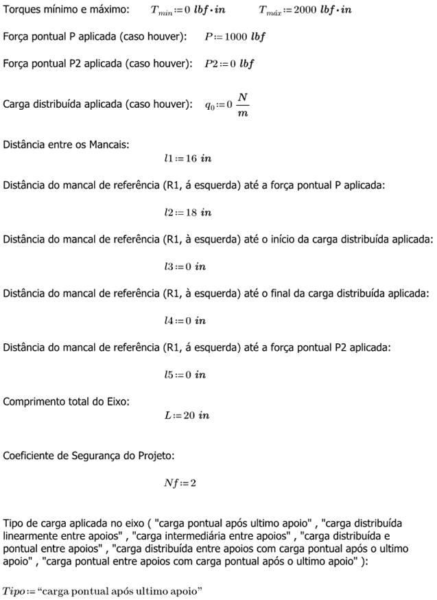
Null data do not interfere in the calculations, because, once the program is automated, the software understands that they are values that are not necessary to solve this problem (point load after the last support). In addition to these data, others are important for the resolution of the exercise: referring to fatigue. Figure 4 shows these values (in yellow), which in turn can also be edited by the user.
Figure 4 – Data for fatigue
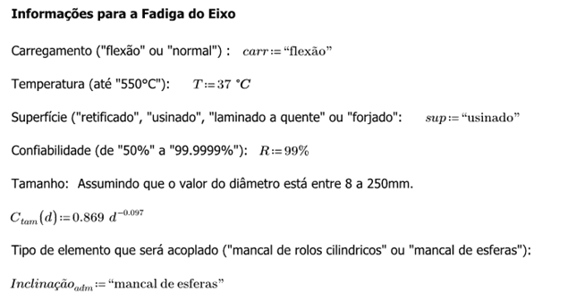
The last information “ball of bearing supports” will not be useful in this example, as the exercise only asked for the diameter in relation to the fatigue load and not to correct with the allowable deflection (correction in relation to the geometry). A special note regarding the “Size” information, in addition to being non-editable, is that the program was designed to dimension shafts with a diameter of up to 250 mm.
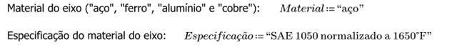
In addition, two other pieces of information are crucial for automated calculations: the Material and its Specification. As for the latter, there is a list of specifications in the software entirely taken from Appendix A of the book by Norton (2013) worked here. Both are used to obtain, with greater precision, the values of Maximum Tensile Strength (Sut) and Yield Resistance in Tensile (Sy). From these values, the axis will be dimensioned according to the ASME method.
Figure 5 – Material and Specification
Thus, the shaft design is complete for its dimensioning. The result obtained was:
Figure 6 – Result obtained from Example 1

It can be noted that the result obtained (Figure 6) was the same as Norton’s response, shown in Figure 2. Thus, the automation of the shaft dimensioning process was a success in this case.
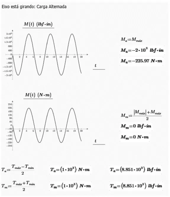
As mentioned in item 1, the project presented here is also intended to help in the academic field. Doing justice to this part, it presents the support reactions, the shear force (shear) and internal bending moment diagrams, the behavior of the shaft under alternating load, the alternating and average components of the internal bending moment, together with the values of the alternating and average torque components. Figure 7 presents the results of reactions at supports and diagrams of internal efforts of comparative exercise I.
Figure 7 – Reactions and diagrams
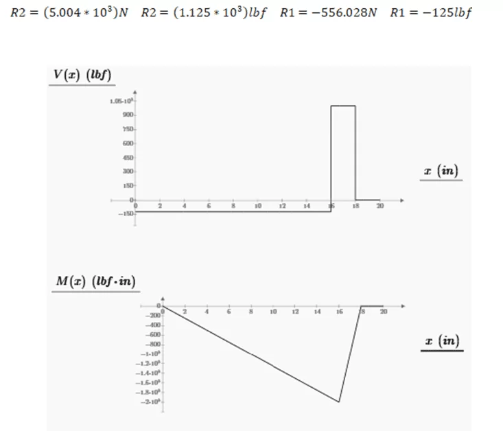
Figure 8 – Alternating and average moments and torques
The project, moreover, also presents the ideal bearing supports for such shaft, whether self-aligning rollers or rigid ball bearings. However, in this comparative example, nothing more is asked than the dimensioning of the shaft in relation to fatigue. The next example will address the bearing support design.
In this example, the software was actually automated in its calculations, generating a response identical to that found in Norton’s (2013) Work Projeto de Máquinas: Uma abordagem integrada.
3.2 PROJECT PROBLEM 2
This problem is a continuation of the previous one, where the selection of the deep groove ball bearing support is now requested. The exercise statement is below:
Figure 9 – Problem 2
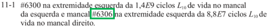
Norton’s (2013) response to the design problem in question presents two different bearing supports . However, for compliance, the design software will choose only one, which will be the bearing support that supports the greatest load. In the problem, the bearing support that undergoes the greatest effort is the one under the support of reaction 2 (R2), as can be seen in Figure 7 due to the greater reaction value. In Figure 10 is the answer to Problem 2 (in green).
Figure 10 – Answer to the second exercise
To automate the project, it is necessary to include the following information, shown in Figure 1:
Figure 11 – Problem data for bearing support
The software admits input in hours and number of cycles for the life of the bearing support, in this way projects can be made that have one data or the other. The response received was:
Figure 10 – Result of the ball bearing support obtained from Example 2

Note that the answer was not the same and that the shaft diameter value is different. The reasons for these differences are suitability and security. The bearing supports present in the SKF manufacturer’s catalog have specific diameters for each load, whether dynamic or static. Thus, it was necessary to carry out an automated rounding within the program to adapt to the types of bearing supports present. And, for safety reasons, the rounding was carried out as follows: approximating every 5 mm. Using this exercise as an example, the diameter value was 30.2 mm, so its rounded value is 35 mm.
Thus, the result obtained was different, since the Norton (2013) result does not have this type of rounding. However, the response can be considered reliable, since a bearing support equivalent to the new diameter was presented, which is larger and more resistant than the minimum necessary for fatigue.
For design purposes, the software also features the equivalent option of a spherical roller bearing support. Changing from “ball rigid” to “self-aligning rollers” as shown in Figure 9, the program displays the bearing support from the respective SKF catalogue.
Figure 12 – Result of the roller bearing obtained from Example 2

This option is not found in Norton’s answers (2013) so that a comparison can be made. However, the specifications of both catalogs were used for the calculations, in an automated way. The response varied the shaft dimension also in this configuration, since the types of bearing supports have different categories and formulations to adopt one for a project.
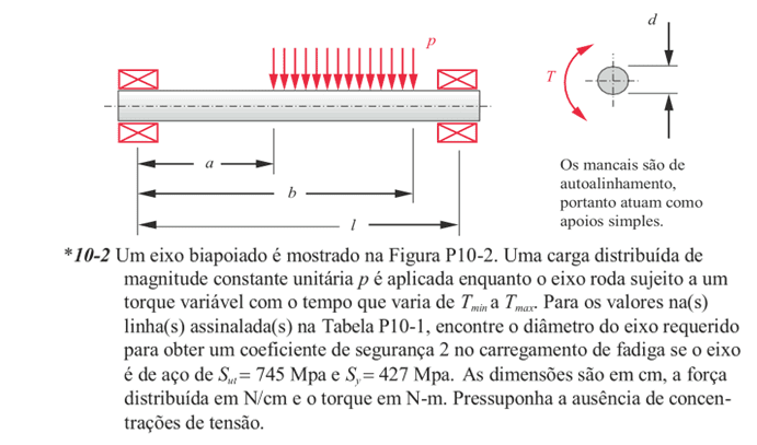
3.3 PROJECT PROBLEM 3
The following exercise is a design problem in which a simply supported shaft undergoes a linearly distributed load between its supports.
Figure 13 – Problem 3
The table cited in the statement is the same as Table 1 used in the first example. The answer found in the handout is:
Figure 14 – Answer to the third exercise

After changing the initial data, shown in Figure 3, and also changing the unit from the English System to the International System, the result obtained was:
Figure 15 – Result obtained from Example 3
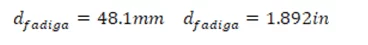
It can be noted that the result was different from Norton’s (2013) response. The program developed to automate the dimensioning of axes has a slight variation in relation to the real one. Table 2 quantitatively presents the errors calculated by comparing the values obtained by the project with those from the Wolfram Alpha website, since their results are the same as those found in the book Machine Design: An Integrated Approach (NORTON, 2013), used here as a base.
Table 2 – Expected errors in the project
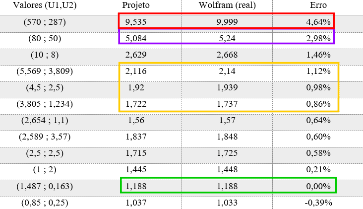
The values named U1 and U2 are the values of the units named in the program for calculating the shaft diameter. Note that the greater the values of these units, the greater the predicted error. As the project in question calculates a shaft of up to 10 inches, or 250 mm, the biggest error found is at the top of the frame (4.64%). In green is the reason why Example 1 has the same result as the real one, having these exact values of U1 and U2, whose error is equal to 0%. In yellow, the error range of Example 3 presented here is located. In the project, the value of U1 was 3,235 and U2 equal to 1,447, both in cubic inches.
Thus, the error of the response in Example 3 was approximately 1%, equivalent to 0.5 mm in this exercise. This error does not prove to be catastrophic, because, as shown in Example 2, the shaft diameter will be rounded to the next unit multiple of 5 for adequacy and safety purposes. That is, both for the Norton response (48.6 mm), which the value is exact and does not have any adjustments, and for the program result (48.1 mm), the value will be 50 mm.
However, for errors greater than 3%, the program will adapt to add another 5 mm. This is because, observing the value marked in purple in Table 2, the error ends up being around 4 mm, and not more than 0.5 mm as seen in the example in the previous paragraph. And, for errors greater than 4%, in the red range, 12 mm will be added, since errors can vary up to this value. As an example, the axis considered as real in the red range is approximately 10 inches (250 mm) with an error of 4.65%. Thus, the automated program would result in a value that is 0.464 inches (11.8 mm) smaller. By adding the value of 12 mm, this value would be closer to the real value and, for other slightly smaller dimensions, but with an error still greater than 4%, the sizing would be greater, thus increasing the safety of the project.
It is worth remembering that, after the addition, the value obtained will be rounded to the next multiple of 5. So, still using the red band as an example, the axis of the Project was 9.535 inches, or 242.2 mm. Adding another 12 mm, your result is 254.2 mm, and rounding, your final answer is 260 mm. This last value is the maximum diameter value that the program has to adopt a rolling element bearing support. If the static or dynamic load requires a larger diameter to fit a bearing support, the program will respond with a message “Adopt another material”, since the maximum value is 260 mm
Thus, the dimensioning of the axis is operating in order to suit the academic and professional scope, which operate in the ASME method for calculations.
3.4 OTHER TYPES OF DESIGN PROBLEMS
In addition to the problems presented above, the project was also programmed to solve the following cases:
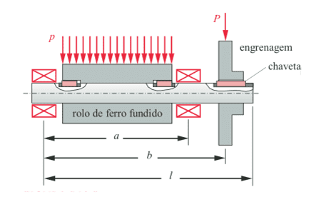
Load distributed between supports with point load after the last support;
Figure 16 – Roller driven by gear
Point load between supports with point load after the last support;
Figure 17 – Gears on a common shaft
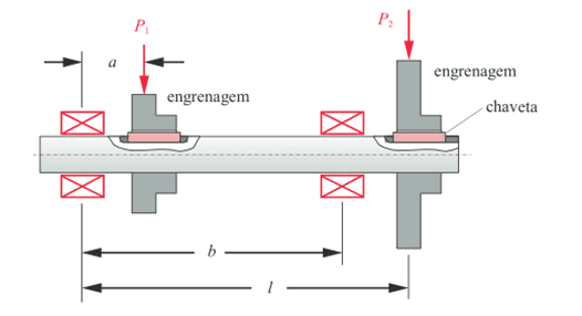
Intermediate load between supports, which would be similar to Figure 17 without the second gear with the load named P2;
Distributed and punctual load between supports, which in turn, analogously, would be as if the gear in Figure 16 were located in the same space as the roller.
Thus, the developed program is capable of solving six types of design problems. It is worth remembering that the requesting efforts diagrams are presented for all, aiming at understanding in obtaining the answers in the academic environment.
4. CONCLUSION
The project developed and presented here aims to optimize the shaft sizing process, making a software perform the calculations in an automated way.
It proved to be effective to obtain the diameter of a shaft in relation to fatigue and safety in items 3.1. and 3.2. In item 3.3. errors were presented along with their corrections within the program.
There are calculations in the program that represent the correction of this first diameter in relation to a geometric factor. This, in turn, was not requested in the examples worked on in item 3, having examples in the work Mechanical Engineering Project (SHIGLEY; MISCHKE; BUDYNAS, 2005). Examples from such a book were not used since, as the calculations and tabulated values, such as breakdown voltages, are based on Projeto de Máquinas: Uma abordagem integrada (NORTON, 2013) the results would not be the same.
In addition, the program has the necessary corrections regarding the existence of a keyway and in relation to a rolling element bearing support, as shown in the example of item 3.2. Emphasizing here that the maximum limit of a shaft design here is 250 mm.
The use of Mathcad Prime 5.0 software allowed the automation of all the processes mentioned in the paragraphs above. In addition, it presented the diagrams and their results so that it serves both for an axle manufacturing industry and for the understanding of students of mechanical engineering courses.
Finally, the developed program proved to be a success for several mechanical projects that depend on a key part. As Norton (2013) states, all machines that operate with rotating movements have this component for their operation. This part is essential for the maintenance and evolution of countless pieces of equipment and machinery around the world: the axle.
REFERENCES
COLLINS, J. A. Projeto mecânico de elementos de máquinas: Uma perspectiva de prevenção da falha. Rio de Janeiro: LTC, 2006. 740 p.
DAMAS, L. Linguagem C. 10.ed. Rio de Janeiro: LTC, 2007. 410p.
FERREIRA, S.E.; CAMPOS, F.O.; DIAS, A.O. Softwares em ambientes educacionais. 2017. 8f. Artigo do Depto. De Computação da Universidade do Estado de Mato Grosso (UNEMAT) – Campus de Alto Araguaia, Mato Grosso, 2017.
HIBBELER, R.C. Resistência dos materiais. 7. ed. São Paulo: Pearson, 2010. 641 p.
JUVINALL, R. C.; MARSHEK, K. M. Fundamentos do projeto de componentes de máquinas. 4. ed. Rio de Janeiro: LTC, 2008. 500 p.
SOUZA, E. D. D. Análise do efeito da tensão média sobre a resistência à fadiga do aço ASTM A743 CA6NM. 2011. 32f. Trabalho de conclusão de curso – Universidade de Brasília, Brasília, 2011.
NIEMANN, G. Elementos de máquinas. São Paulo: Edgar Blücher, 1971. 184 p.
NORTON, R. L. Projeto de Máquinas: Uma abordagem integrada. 4. ed. Porto Alegre: Bookman, 2013. 1056 p.
PINHEIRO, V.; NOGUEIRA, L. M.; COSTA, A. L. M. Algoritmo para análise gráfica e dimensionamento de eixos de transmissão de potência. 2014. 8f. Trabalho para XIV Congresso Nacional de Engenharia Mecânica e Industrial – FENEMI, Salvador, 2014.
SHIGLEY, J. E.; MISCHKE, C. R.; BUDYNAS, R. G. Projeto de engenharia mecânica. 7. ed. Porto Alegre: Bookman, 2005. 960 p.
WOLFRAMALPHA. Computational intelligence. Disponível em: < https://www.wolframalpha.com/> Acesso em: 10 set. 2020.
[1] Degree in Mechanical Engineering.
[2] Advisor.
Shipped: January, 2021.
Approved: May, 2022.