ORIGINAL ARTICLE
JANCHIKOSKI, Aline Ribeiro [1], MEIRELES, José Filipe Bizarro [2]
JANCHIKOSKI, Aline Ribeiro. MEIRELES, José Filipe Bizarro. Dynamic analysis of a free vibrating cantilever beam. Multidisciplinary Scientific Journal Nucleus of Knowledge. Year. 08, Ed. 06, Vol. 01, pp. 123-142. June 2023. ISSN: 2448-0959, Access link: https://www.nucleodoconhecimento.com.br/engineering-mechanical-engineering/dynamic-analysis, DOI: 10.32749/nucleodoconhecimento.com.br/engineering-mechanical-engineering/dynamic-analysis
ABSTRACT
This paper has as subject a theoretical, numerical and experimental study of the behavior of a 1.5 meters long and cross section of 0.02 meters wide and high beam. The main objective was to analyze a structure, in this case it was a cantilever steel beam, to establish the possible solutions that best define the behavior of this structure, to obtain the results and to prove the veracity of the results obtained by means of an experimental analysis method. In this sense, essential theoretical foundations were used for the understanding and realization of the mathematical formulations of this project, in order to obtain the analytical results of the vibration modes of the beam and respective natural frequencies. To complement the analysis of the beam behavior, the finite element method procedure was applied using the ansys software to obtain more accurate results. The results obtained for the beam from these two methodologies include bending modes among the first 10 degrees of freedom. To validate the study done previously a physical model of the beam was used for the experimental test, for this it was defined that the equipment for measuring the resonance frequencies would be a digital stroboscope, enabling the measurement of only 8 vibration modes due to its small frequency range.
Keywords: Cantilever beam, Ansys software, Ansys parametric design language, Modal analysis, Vibration modes.
1. INTRODUCTION
This paper has as main interest the dynamic study of the behavior of a structure from an analytical, numerical and experimental analysis. The structure in question is a cantilever square beam, in which the oscillatory behavior of the first ten vibration modes and their respective natural frequencies will be addressed.
The object of study of this project is the oscillatory motion caused by vibrations, these vibrations exist in nature in organic or forced form. It is possible to state that this research area is an important aspect of engineering that should be deepened and understood so that the projects executed are successful.
Modal analysis is the ideal tool to study the behavior of structures, since the structure can be analyzed in its naturals vibration modes without the need to simulate specific situations of acting forces. One of the means to determine the behavior of a structure is from the analytical analysis, in which the structure or mechanical component is simplified into a system of one or more degrees of freedom. A solution of these systems is by means of equations of motion that characterize the exact behavior to be studied, resulting in the knowledge of the natural frequencies and the respective vibration modes.
For more complex structures the numerical method is used, in which case a numerical simulation of the structure with well defined initial and boundary conditions in which are applied the principles of the finite element method, using the theory of modal analysis to solve the problems. The experimental analysis is used to prove the study done previously made by other means.
The problematic of study of this work aims at the use of a 1.5 meters length beam in order to dedicate to the visualization of the oscillatory movements caused by the resonance frequencies.
The general objective of this paper is to analyze a structure, establish the possible solutions that best define the behavior of this structure, obtain the results and prove the veracity of the results obtained by means of an experimental analysis method.
To obtain the results, first the analytical method will be used, then the ansys software to the numerical method. To validate the results of both methods, the experimental method will be used for the physical model in question, according to the initial and boundary conditions defined.
2. THEORETICAL GROUND
Modal analysis is an analytical methodology commonly used to predict the vibratory behavior of a structure. The analysis by this criterion can be done numerically and experimentally, using mathematical models that best translate the real behavior of the project to be studied.
With the study of dynamic behavior made from modal analysis, it is possible to characterize the structural dynamic properties, including modal parameters, such as resonance frequencies, associated vibration modes and damping factors. These particularities represent the behavior of vibrations when subjected to external loads, and depend on the mass, stiffness and attenuation of movement along the component or structure to be studied (SORIANO, 2014).
Modal analysis is easily done analytically for more basic components, but in situations where the structures studied are more complex, it is necessary to use computational techniques, namely the Finite Element Method (FEM).
FEM is a mathematical analysis capable of describing complex and irregular geometries in differential equations, starting from the fragmentation of the geometry into smaller elements that have the same properties as the original element, in which the solution is obtained by means of mathematical models associated with each type of study (LOTTI et al., 2006). The finite element method is a technique which aims to find the solution to a complex problem by replacing it by a finite number of elements of much simpler solutions, whose mathematical formula indicates a very approximate answer to the original problem through differential equations [3] .
The resolution is done individually for each element, where this element is connected to other elements through the contour boundaries, which form the domain of the structure/component and the final analysis is around the global solution of the results of all existing elements. The calculation process involves the discretization of the region of interest of the problem into several finite elements, usually for two-dimensional area problems is done through small rectangles, but it can also be done with triangular elements. Other techniques, as the discretization using hexagonal or octagonal elements, can also be used.
These techniques use polynomial approximations, such as splines, to approximate the solutions of the partial differential equations. The partial differential equations are then transformed into linear algebraic equations representing the forces and deformations at the boundary points of each element. These algebraic equations are then solved for the unknown parameters from numerical solution techniques, which can be by the Galerkin method, the limited Galerkin method and the linear or nonlinear finite element method [3].
Once solutions are found for each element, the continuity principles are used to calculate the properties of interest in the complete domain. The continuity principle is applied to ensure that all geometrical characteristics of the finite elements are preserved, for this an interpolation of the results is made on the adjacent elements along the boundary.
2.1 MULTIPLE DEGREES OF FREEDOM SYSTEMS
Degrees of freedom (DOF) are defined as the minimum number of independent coordinates that are able to define all parts of a system in any period of time. These coordinates represent a set of generalized coordinates and can be Cartesian or non-Cartesian [4] . A system of multiple degrees of freedom is that in which it needs two or more coordinates to have the movement completely defined.
Most structural and machine systems, when disturbed, exhibit a continuous elastic deformation. Consequently, they need an infinite number of DOF for the complete representation of spatial and time coordinates. These systems are called continuous or distributed [4] . Figure 1 illustrates a system with an infinite number of DOF represented by a cantilever beam.
FIGURE 1: Cantilever beam – System with a infinite number of DOF
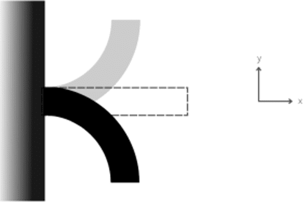
The dynamic analysis of this type of structure is made by applying the laws of Structural Mechanics in which the differential equations must completely characterize its structural behavior. For this, it is also used Newton’s second law at each mass of the system.
FIGURE 2: (a) Example of a 2 DOF system. (b) Generic free-body diagram: Mass-spring-damper system
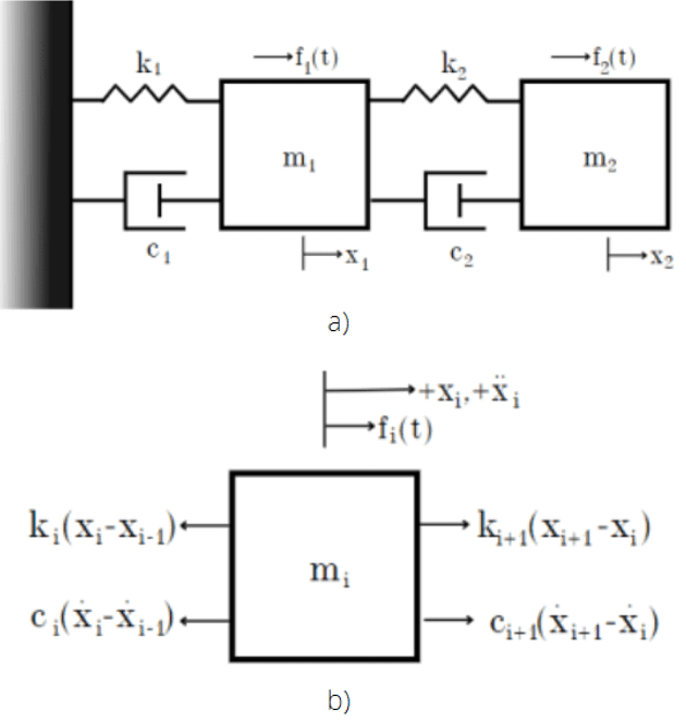
With the generic free-body diagram assembled, from figure 2 (b) the positions of the masses are measured from their respective static equilibrium position, and that the directions of displacement, velocity and acceleration are positive. Applying the principles of Newton’s second law, it is possible to write a generic equation [2.1] which covers a system of n degrees of freedom.
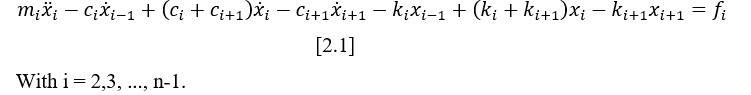
The equations of motion of the system masses [2.2-2.3] can be written from equation [2.1], for the first mass it is taken that i=1 when ![]() .
.
![]() And for the rest of the masses it says that i=n when
And for the rest of the masses it says that i=n when ![]() .
.
![]() The existing analytical methods for continuous systems cannot deal with every type of system, they are limited to solving only a small range of very simple problems involving uniform beams, thin rods and plates. Practical discretized models are approximated as discrete systems and treated as concentrated finite masses, springs or concentrated finite dampers [4].
The existing analytical methods for continuous systems cannot deal with every type of system, they are limited to solving only a small range of very simple problems involving uniform beams, thin rods and plates. Practical discretized models are approximated as discrete systems and treated as concentrated finite masses, springs or concentrated finite dampers [4].
If a system continues to vibrate even after the initial external disturbance is ceased, it is a free vibration system, in which no external force of any kind is affecting the system [4].
A system, when suffering an external disturbance, presents a vibration frequency associated, if this frequency coincides with any of the natural frequencies of the system, there is a resonance phenomenon and the resulting oscillations are harmful. The natural frequencies of a system represent how freely a mechanical component or structure vibrates after the applied external force has been stopped, and may have multiple natural frequencies in various directions. For dynamic study, the most important resonance frequency is the first, called fundamental, it is the smallest of all and is always the one that prevails more in the oscillatory movement [5].
In a damped system, part of the energy during oscillation is dissipated or lost, in which case a damped vibration is observed. In a free vibration system, the damping portion of the equilibrium equation has a low influence on the vibration frequency. In real structures, damping is not always totally linear, in these cases an equivalent damping coefficient is used [6].
3. DYNAMIC ANALYSIS
The structure to be analysed in this project is illustrated as follows
FIGURE 3: Cantilever beam
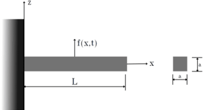
The dimensions to be studied will be L=1.5 meters long, with a width and height of a=0.02 meters. Initially the numerical and analytical calculations will be made for a generical steel beam.
3.1 ANALYTICAL FORMULATION
The analytical analysis in question will be performed for a beam embedded in one end and free at the other end that suffers a free vibration, i.e., there are no external forces applied. The vibration of the beam will generate displacements and deformations that are due to the efforts of bending, from that will be predicted the frequencies required for the occurrence of such movement, within the first 10 DOF.
The first boundary conditions defined translate, the embedded behavior in which the displacement and rotation of the end are non-existent [3.1] and the end is in the initial position x=0 of the plane [3.2].
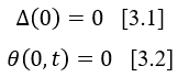
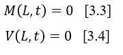
At the free end, x=L, it is verified by the equations that the bending moment [3.3] and the shear force [3.4] are also non-existent.
The general equation of motion [3.5] describes the bending motion of the beam due to vibrations.
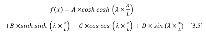 By replacing the boundary conditions defined previously in equation [3.5], four new equations are obtained [3.6, 3.8, 3.10, 3.12].
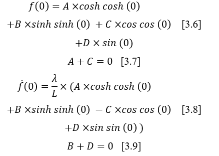
Equations [3.7] and [3.9] represent the boundary conditions of the recessed end.
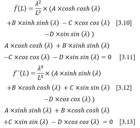
Equations (3.11) and (3.13) represent the free end boundary conditions. By simplifying and rearranging the above equations, the system of equations [3.14] is obtained.
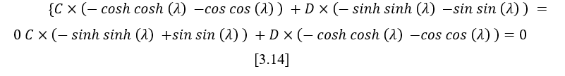
To solve the system above, it is necessary to transform it into a matrix [3.15] in which the determinant of the matrix of coefficients C and D are null.
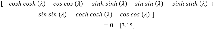
From the result of the matrix determinant, it is obtained the characteristic equation [3.16] that represents the behavior of the cantilever beam.
![]()
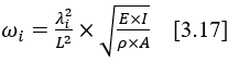
The natural frequency equation for an undamped free vibration is given by equation [3.17]
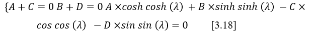
The equations for the characteristic bending vibration modes of the beam are found by solving a triple system [3.18] of the equations found for the boundary conditions.
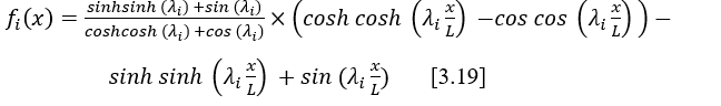
By rearranging the system and solving for one of the constants, such as the D and substitute it into the general equation of motion [3.5]. To simplify the equation, we impose that the value of the constant D takes the value of 1, thus, the equation of vibration modes of the system of a catilever beam is given by the equation [3.19]
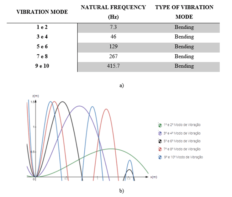
With the analytical study of the beam it is possible to define the type of vibration mode seen among the first ten DOF, with their respective natural frequencies. The results are shown in figure 4.
FIGURE 4: (a) Types of vibration modes and their beam frequency. (b) Overlap of the 10 DOF of the beam.
3.2 NUMERICAL ANALYSIS
For the numerical analysis it is necessary to define the geometry of the beam, the material and the boundary conditions that characterize the behavior to be studied. It was made a simulation for the first 15 DOF, but the main goal is to see the first 10 bending vibration modes.
The mesh element used was the linear mesh with a size of 10 mm, which provides uniformity in the arrangement of elements along the geometry, ensuring a more accurate result. In all, there are 600 elements and 4521 discrete nodes in the beam, these elements are connected at four points, which means that they have four nodes and each one with two coordinates to define its geometric location.
For the boundary condition it was applied a fixed constraint in x, y and z axes on the face of one of the beam ends. The fixed constraint is applied through displacement constraints, where it is defined that no deformation, displacement or rotation are allowed for this element. The natural frequencies found for the first 15 DOF are presented in figure 5 and among them are the bending, tensile/compression and torsional natural frequencies. As seen, among the first 10 DOF there are only bending vibration modes.
FIGURE 5: Natural frequencies of the 1.5m long beam from numerical analysis
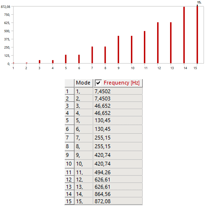
Source: Elaborated by the author, 2023.This graphic shows the vibration mode on the abscissa axis and the respective frequency on the ordinate axis. The representations of the vibration modes of each frequency are illustrated in figure 6.
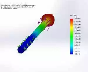
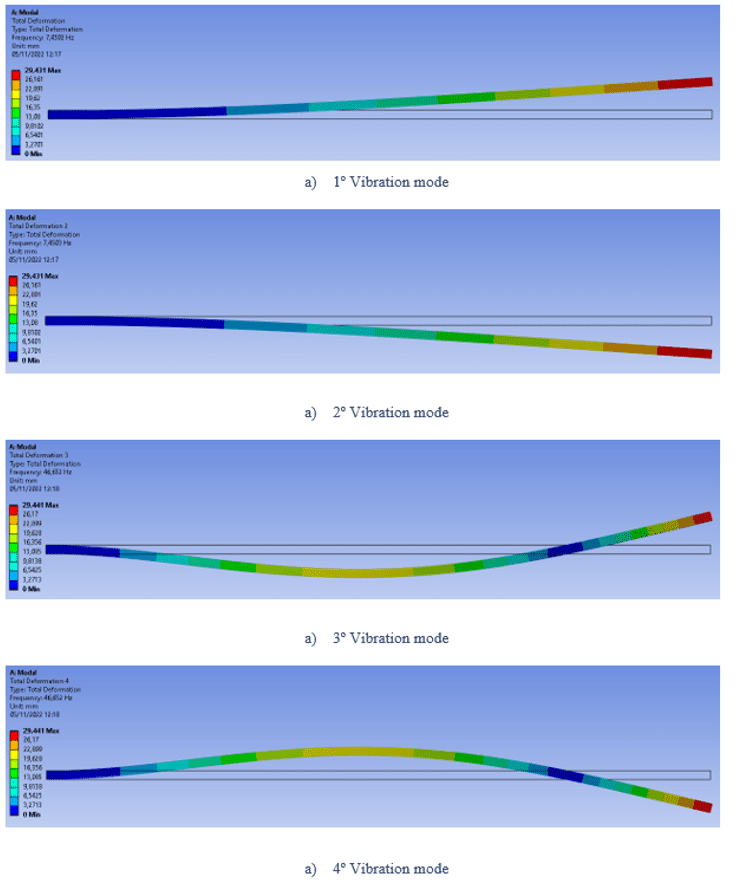
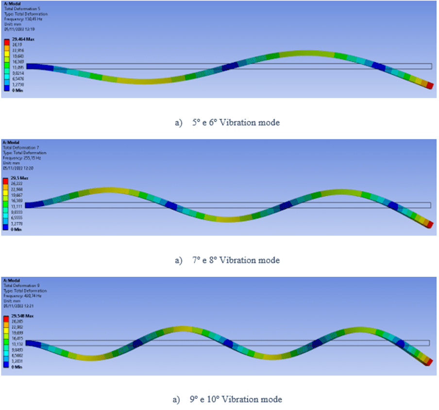
FIGURE 6: Representation of the first 10 vibration modes of the beam by ANSYS
To perform the numerical simulation of the beam, it is also possible to use the ansys parametric design language (APDL) in order to parameterize the beam length. APDL is a programming language made to create and modify finite element models in ansys code.
The APDL uses a method of matrix development that is based on finite element theory. The matrix development method is used to construct the global stiffness matrix of the system which is used to estimate the natural modes and the associated frequencies. With the definition of the pre-processing through APDL a 3D model of the beam under study is obtained, represented by figure 7 (a). The pre-processing part begins with the definition of the element type, for this study the element is indicated by figure 9 (b).
FIGURE 7: (a) 3D Modeling of the beam by ANSYS parametric language. (b) Element type for simulation in APDL
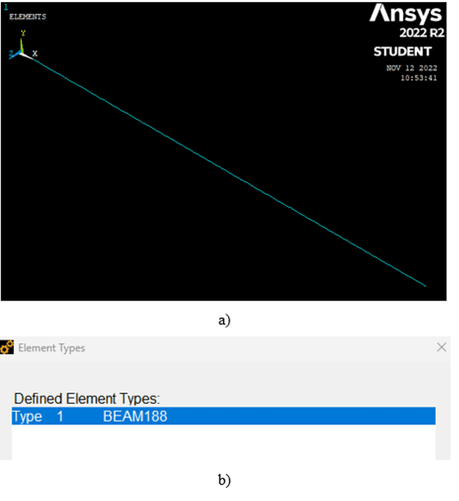
The size of the mesh element was 10 mm. The BEAM188 element is a 3D beam element with six DOF at each node of the element, three of them are rotational and three translational, developed by ansys for structural engineering applications. This type of element is based on a finite element theory of second order, i.e., a local coordinate system and local deformations are used to describe the behavior of each node.
The modelling is build through two nodes, the first node corresponds to the end (0,0) and the second node is defined by the coordinates (0,1.5). For the results, a total of 10 steps was defined, which corresponds to the first 10 frequencies found can be seen at table 1.
Table 1 – APDL analysis results for the 1.5m long beam
| VIBRATION MODE | APDL NATURAL FREQUENCY (Hz) |
| 1 e 2 | 7.4447 |
| 3 e 4 | 46.725 |
| 5 e 6 | 131.27 |
| 7 e 8 | 258.61 |
| 9 e 10 | 430.63 |
Source: Elaborated by the author, 2023.
3.3 EXPERIMENTAL ANALYSIS
The structure assembled to perform this experimental analysis includes an amplifier, a CB Piezotronics 221B02 load cell, a PCB Piezotronics 356A14 accelerometer, a LDS V201 exciter and a data acquisition system equipment connected to a computer with a LMS Siemens V10 software for the analysis. The boundary conditions previously imposed by equations [3.1] through [3.4] can be verified in figure 8. The recessed end was clamped in a bench vice which was fixed on a gantry, and the other remained free without any kind of support.
FIGURE 8: Experimental structure of the 1.5m long beam
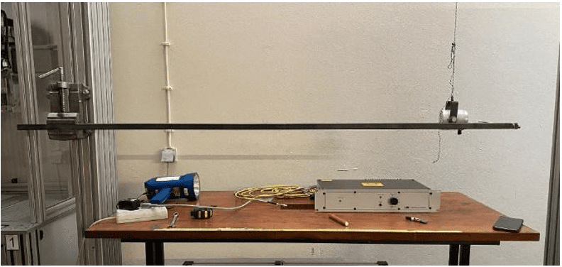
A Nova Strobe brand DBX Xenon digital strobe with a maximum frequency measurement limit of 330 Hz was used. Due to the limitation of the frequency range, only the first eight vibration modes were verified, which correspond to four different values of resonance frequencies, indicated in the table 2.
Table 1 – Experimental results of the 1.5m long beam
| VIBRATION MODE | EXPERIMENTAL NATURAL FREQUENCY (Hz) |
| 1 e 2 | 6.92 |
| 3 e 4 | 45.87 |
| 5 e 6 | 132.05 |
| 7 e 8 | 260.23 |
Source: Elaborated by the author, 2023.
4. ANALYSIS OF THE RESULTS
Due to the beam cross-sectional geometry, the bending natural frequencies found tend to be symmetric in all directions, resulting in vibration modes also symmetric. The percentage difference between the values of the resonance frequencies found analytically and by the theoretical analysis of ansys is due to the precision of the type of analysis method used.
With the results obtained through the experimental analysis of the physical model of the beam, it is possible to compare the results with the other two analysis performed, analytical and numerical. With the stroboscope it was only possible to measure the first eight DOF that correspond to the bending movements of the beam, and that the measured values are close to the expected theoretically, which indicates that the instrument was effective to perform the measurement of the frequencies of the vibration modes presented.
5. FINAL CONSIDERATIONS
The main focus of this project was the study of resonance vibrations and their vibration modes. Analytical and numerical analysis predict the dynamic behavior of the structure and the other one validates experimentally the results obtained by using of a physical model.
The results of the analytical formulation, for the first 10 naturals frequencies, were found bending vibration modes. With the first part of the analysis it was possible to conclude that the bending mode is seen from very small stimulus of external loads, and consequently are the first to appear in such a structure. The most important natural frequency is the fundamental, which corresponds to the lowest frequency to which a vibrating system responds, and it is from where the other vibration modes of the same system are generated.
Among the results found by analytical and numerical formulation is then concluded that the percentage error between these two types of analysis is not very discrepant, and some of the reasons for this are the differences in the methods used to find the equations of motion that characterize the behavior of the beams, in which analytically it is done through the fundamental principle of dynamics and the D’Alembert principle and numerically is done through the finite element method. Besides approximations and rounding of decimals in the resolution of the equations analytically.
After performing the experimental analysis with the physical model of the beam, it was observed that the measuring instrument chosen to measure the natural frequencies does not have a the range of values sufficient to contemplate all the natural frequencies predicted by the other methods, therefore it was concluded that the stroboscope provided to this study is only viable for use in situations of low operational frequencies or in which it is not possible to have access to or direct contact with the component under study.
ACKNOWLEDGEMENTS
I would like to express my sincere gratitude to my supervisor, José Filipe Bizarro Meireles, for his constant support and guidance throughout the process of this research.
And to the University of Minho who provided access to the resources and equipment of the research laboratory.
REFERENCES
SORIANO, H. L. Introdução à dinâmica das estruturas. Elsevier. 2014.
LOTTI, R. S., et al. Aplicabilidade científica do método dos elementos finitos. R Dental Press Ortodon Ortop Facial, v. 11, n. 2, pp. 35–43, 2006. Available in: <https://doi.org/10.1590/S1415-54192006000200006>. Acess in: 01 may. 2023.
[3] RAO, S. S., ATLURI, S. N. The Finite Element Method in Engineering. Journal of Applied Mechanics, 1983. Available in: <https://doi.org/10.1115/1.3167179>. Acess in: 01 may. 2023.
[4] RAO, S. S. Mechanical vibrations (3a ed.). Addison-Wesley, 1995.
[5] BOLINA, C. C. et al. Vibrações: As frequências naturais estimada e experimental de uma estrutura. In: CONGRESSO NACIONAL DE MATEMÁTICA APLICADA À INDUSTRIA, 2014, Caldas Novas, Goiás. Available in: <10.5151/mathpro-cnmai-0038>. Acess in: 02 may. 2023.
[6] BACHMANN, H.; et al. Vibration Problems in Structures, Practical Guidelines. Birkhäuser verlag, 1997. Available in: https://doi.org/10.1007/978-3-0348-9231-5. Acess in: 02 may. 2023.
VINSON, J. R., SIERAKOWSKI, R. L., BERT, C. W. (1987). The Behavior of Structures Composed of Composite Materials. Journal of Applied Mechanics, 1987. Available in: https://doi.org/10.1115/1.3172985.
HARTOG, J. P. D. Mechanical vibrations (4a ed.). McGraw-Hill, 1956.
NETTO, A.B.R, ARAUJO, R.R. Comparação das frequências naturais e modos de vibração de vigas metálicas biapoiadas com uma e duas almas senoidais utilizando o ANSYS. Projectus, 3(1), 125–139, 2020. Available in:<file:///C:/Users/User%20-%20005/Downloads/631-Artigo-1895-1-10-20200721.pdf >. Acess in: 02 may. 2023.
GOMES, A.V.S.; et al. Análise de vibrações de vigas bi-engastada e engastadas e livres: Estudo numérico e experimental. XIII SIMMEC, 2018. Available in: <https://doity.com.br/media/doity/submissoes/artigo-fdeec275083202197886be2da299d920f82af3ea-arquivo.pdf>. Acess in: 02 may. 2023.
PÉREZ, M., et al. Desenvolvimento de um sistema experimental para a determinação de frequências próprias de vibração. Revista da Associação Portuguesa de Análise Experimental de Tensões, 2013. Available in: <http://www-ext.lnec.pt/APAET/pdf/Rev_24_A3.pdf>. Acess in: 02 may. 2023.
CHAPHALKAR, S.P, KHETRE, S. N., MESHRAM, A. M. Modal analysis of a cantilever beam structure using finite element analysis and experimental analysys. (pp. 178–185). American Journal of Engineering Research, 2015. Available in: <https://www.academia.edu/27362678/Modal_analysis_of_cantilever_beam_Structure_Using_Finite_Element_analysis_and_Experimental_Analysis>. Acess in: 02 may. 2023.
RODRIGUES, A. F. S. Vibrações transversais em vigas finitas sujeitas a cargas móveis: radiação de transição associada à mudança brusca da rigidez vertical de fundação [MasterThesis, Faculdade de Ciências e Tecnologia]. RUN – Repositório da Universidade Nova de Lisboa, 2009. Available in: http://hdl.handle.net/10362/3925.
MENDES, P. T. F. Análise dinâmica de uma estrutura: Estudo numérico e experimental. [MasterThesis, Intituto Superior de Engenharia de Lisboa]. RICPL – Repositório Científico do Instituto Superior de Engenharia de Lisboa, 2012. Available in: <https://core.ac.uk/download/pdf/47131588.pdf >. Acess in: 02 may. 2023.
BRAGA, C. A. S. T. Caracterização de um ensaio de análise modal recorrendo a leitura sem contacto [MasterThesis, Universidade do Minho]. RepositóriUM – Repositório Institucional da Universidade do Minho, 2014. Available in: http://hdl.handle.net/1822/34352.
GUIMARÃES, P. V. S. Ensaios de vibração para determinação dos parâmetros dinâmicos de estruturas [MasterThesis, Universidade do Minho]. RepositóriUM – Repositório Institucional da Universidade do Minho, 2012. Available in: <http://repositorium.sdum.uminho.pt/handle/1822/29792>. Acess in: 02 may. 2023.
MEIRELES, J. F. B. Análise dinâmica de estruturas por modelos de elementos finitos identificados experimentalmente [DoctoralThesis, Universidade do Minho]. RepositóriUM – Repositório Institucional da Universidade do Minho, 2008. Available in: <https://repositorium.sdum.uminho.pt/bitstream/1822/8059/1/PHD-Meireles%20Revision%208e.pdf>. Acess in: 02 may. 2023.
MALLIKARJUNA, A., RAJU, P. K., SHANG, D. Modal analysis of coupled structures and parametric relation of the coupled and uncoupled natural frequency of cylinders by finite element analysis. International Journal of Engineering Applied Sciences and Technology, 04(04), 2019, pp. 323–335. Available in: <https://www.academia.edu/60224188/Modal_Analysis_of_Coupled_Structures_and_Parametric_Relation_of_the_Coupled_and_Uncoupled_Natural_Frequency_of_Cylinders_by_Finite_Element_Analysis>. Acess in: 02 may. 2023.
HE, J., FU, Z.-F. Basic vibration theory. In: Modal Analysis , pp. 49–78, 2001. Elsevier. https://doi.org/10.1016/b978-075065079-3/50003-6.
CARNEIRO, V. H., Puga, H., Meireles, J. Positive, zero and negative Poisson’s ratio non-stochastic metallic cellular solids: Dependence between static and dynamic mechanical properties. Composite Structures, 226, 111239. 2019. Available in: https://doi.org/10.1016/j.compstruct.2019.111239.
SCHMITZ, T. L., SMITH, K. S. Single Degree of Freedom Free Vibration. In: Mechanical Vibrations, pp. 29–87, 2020. Springer International Publishing. Available in: https://doi.org/10.1007/978-3-030-52344-2_2.
BENAROYA, H., NAGURKA, M. Multi Degree-of-Freedom Vibration: Introductory Topics. In: Mechanical Vibration, pp. 541–644, 2009. CRC Press. Available in: https://doi.org/10.1201/9781420080575-13.
MENARD, K. P. An Introduction to Dynamic Mechanical Analysis. In: Dynamic Mechanical Analysis. CRC Press, 1999. Available in: https://sv.20file.org/up1/608_0.pdf.
HE, J., FU, Z.-F. Basic vibration theory. In: Modal Analysis , pp. 49–78, 2001b. Elsevier. Available in: https://doi.org/10.1016/b978-075065079-3/50003-6.
BADING, H. M. Natural Frequencies of Steel Beams. Hassell Street Press. 2021.
BALES, P. D., BLACKBURN, E. A Mechanical Stroboscope. American Journal of Physics, 5(1), 39, 1937. Available in: https://doi.org/10.1119/1.1991163.
AHIWALE, D., MADAKE, H., PHADTARE, N., JARANDE, A., JAMBHALE, D. Modal analysis of cracked cantilever beam using ANSYS software. Materials Today: Proceedings, 56, pp.165–170, 2022. Available in: https://doi.org/10.1016/j.matpr.2022.01.055.
DHATT, G., TOUZOT, G., LEFRANÇOIS, E. Numerical methods. In: Finite Element Method. John Wiley and Sons, Inc., 2013, pp. 345 – 503. ISBN: 9781118569764. doi: 10.1002/9781118569764.ch1.
LIU, G. R., QUEK, S. S. Fundamentals for finite element method. In: Finite Element Method, 2003, pp. 35–66. Elsevier. Available in: https://doi.org/10.1016/b978-075065866-9/50004-9.
[1] Degree in Mechanical Engineering. ORCID: 0009-0006-9109-3805.
[2] Advisor. ORCID: 0000-0003-0881-2348.
Submitted: March 22, 2023.
Approved: April 14, 2023.