ORIGINAL ARTICLE
CARVALHAES, Daniely Silva [1], CARVALHAES, Daniel José [2], QUARESMA, Wanessa Mesquita Godoi [3]
CARVALHAES, Daniely Silva. CARVALHAES, Daniel José. QUARESMA, Wanessa Mesquita Godoi. Comparison of sizing and modeling of columns. Revista Científica Multidisciplinar Núcleo do Conhecimento. Year 05, Ed. 05, Vol. 04, pp. 121-146. May 2020. ISSN: 2448-0959, Access Link: https://www.nucleodoconhecimento.com.br/civil-engineering/modeling-of-columns , DOI: 10.32749/nucleodoconhecimento.com.br/civil-engineering/modeling-of-columns
SUMMARY
The search for the reduction of time in the elaboration of projects becomes a necessity, together with the indigence of understanding recurrent problems in the use of reinforced concrete structures such as pathologies. Thus, uniting the two problems, time and analysis, it becomes imperative to study ways of modeling and analyzing the structures in the common software of project development. The objective is to model a building and compare a structural element, analyzing the loads and dimensions made by the TQS software®. This process is due to the modeling in the TQS software of the example building of José Milton de Araújo (2014). It was observed that the modeling process compared to the numerical process presents significant difference due to the fact of doing the analysis of the complete building, thus being reliable the modeling performed in the software, which allows a previous study of the entire structure.
Keywords: Pillars, sizing, modeling, experimental, TQS.
1. INTRODUCTION
Bastos (2006, p. 07) presents reinforced concrete being “the union of simple concrete and a tensile-resistant material (wrapped by concrete) in such a way that both resist jointly the requesting efforts”, that is the reinforced concrete is the result of the simple concrete plus reinforcement plus adhesion.
For Piancastelli (1997), reinforced concrete is subject to change over time, because it is a non-inert material, thanks to interactions between its constituent elements (cement, sand, gravel, water and steel), interactions between these elements and external agents such as gases, salts, bases, acids and others, and with materials that are added to it (additives and mineral additions).
For a long time the concrete was considered a durable material, due to old works still in good condition, but the early deterioration of current structures leads us to the reasons of concrete pathologies (BRANDÃO and PINHEIRO, 1999). This is due to the new technologies, to make the structures slender and lighter, of the process of planning and production of the structures.
Pillars are elements usually vertically aligned in its axis, in which normal compression forces are preponderant (ABNT NBR 6118, 2014), their study is one of the essential checks, regarding the dimensioning, the malfunction of a pillar of a structure can compromise functionality and cause serious accidents. Being responsible for the transmission of vertical loads, the pillars are generally subject, in particular, to the flexo-compression condition, therefore the need for consideration of second order effects and stability analysis of the pillar as a whole.
The pillars are sized according to the external efforts requesting calculation, which make up the normal forces (Nd), the flaming moments (Mdx and Mdy) and the cutforces (Vdx and Vdy) being horizontal. NBR 6118, in the 2003 version, particularly in rationing the pillars, the standard inserted several modifications, such as the value of accidental eccentricity, a larger concrete cover, a new method in the calculation of the limit slenderness referring to the contemplation or not of the flabby moments of the 2nd order and, above all, with the consideration of the minimum deflector moment, and may replace the deflector moment as a result of accidental eccentricity. The 2014 version added the minimum fletor moment check, made from the comparison of a sturdy wrap, which includes the minimum wrap with 2nd order.
2. CALCULATION AND DIMENSIONING OF PILLARS BY ABACOS
2.1 CLASSIFICATION OF PILLARS
The pillars are classified according to their position in the structure, it can be intermediate, end or corner. This classification allows you to consider the requesting efforts in each calculated situation. (FUSCO,1981)
Figure 1 – Position of the pillars in buildings.
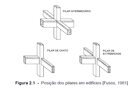
Intermediate pillars are predominantly submitted to axial compression forces, because the phlegm moments are of little intensity, as only to vertical actions (permanent and normal variables). Unless the spans of the continuous beams that are based on these pillars are considered different, the final fling moments transmitted to the pillars are disregarded. Therefore, the intermediate pillar submitted to a compression centered on project situation is admitted, that is, the initial eccentricity, in the dimensioning of the areas of the transverse and longitudinal reinforcements, is considered equal to zero.
The extremity pillars are subjected to normal compression forces and the action of moments propagated by the beams, which have their external extremities supported on these pillars. In the beams transverse to the axis of the interrupted beam, moments are not considered. Therefore, the extremity column subject to composite normal flexion is considered, considering, therefore, initial eccentricity in one of the local ordered of the cross-section of the column.
Corner pillars besides being subjected to normal actuating force, one should consider the moments transmitted by the beams, from which the middle planes are perpendicular to the faces of the pillars, and are interrupted at the edges of the column. In the design situation, the corner column submitted to composite oblique bending is considered, with eccentricities that are initial according to the local coordinated axes.
The pillars, although their classification by their position in the structure is very usual, are also classified as to the type of request that the pillar is submitted. That is, pillars submitted to normal composite flexion, pillars submitted to oblique composite flexion and pillars submitted to centered compression.
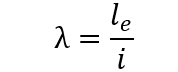
2.2 BELTING INDEX
The slenderness index of reinforced concrete pillars is the ratio between the equivalent length (le) of the column and the rotate radius (i) of the section. (NBR 6118, 2014)
The classification of the pillars depends on the limits of slenderness and additional factors, such as relative eccentricity, the shape of the diagram of moments and the conditions of binding of the ends. These factors are considered using the λ1 coefficient.
For NBR 6118 (2014) short pillars (λ ≤ λ1) the second order effects could be disregarded because the reference indices are higher than the slenderness indices. Median slender pillars (λ1 < λ ≤ 90) which are those for which the second-order effects can be considered by approximate process, as the standard pillar method with approximate curvature. Slender pillars (90 < λ ≤ 140) are those for which it is possible to consider the standard pillar method next to diagrams of M – N – 1/r. Very slender pillars (140 < λ ≤ 200) that require, for the verification of the state of instability limit, the consideration of the exact methods. NBR 6118 does not allow the design and construction of a pillar with a slenderness index (λ) greater than 200. In case of poles with normal force less than 0.10.fcd.Ac, that limit can be exceeded.
2.3 ECCENTRICITIES
In the pillars, eccentricities happen not only because of the initial requests on the pillars, but also because of additional factors such as the effects of 2nd order, the creep of concrete and geometric imperfections.
It is necessary to obtain the eccentricities related to the type of column analyzed to make its dimensioning. This item presents the criteria for obtaining these eccentricities in pillars separately, according to the nbr 6118, 2014 standard.
2.3.1 INITIAL ECCENTRICITY OF 1ST ORDER
We know that the beams and pillars compose three-dimensional gantries, so that the pillars are subjected to composite oblique flexion and, consequently, present initial eccentricities in two main directions. In projects that consider simplified processes for the definition of requesting efforts are fletor moment, normal force and cutting force, for example, the continuous beam case presented in NBR 6118 (2014), it is admitted that the initial eccentricities arise in the corner and end pillars. Remembering that eccentricities are not considered for intermediate pillars.
The eccentricities of the 1st order are given by the expressions: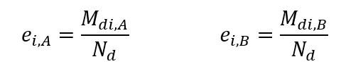
Nd would be the requesting force for calculation;
Md,A and Md,B the requesting moments of calculation at the ends of the column.
The highest eccentricity in absolute value is adopted for ei,A.
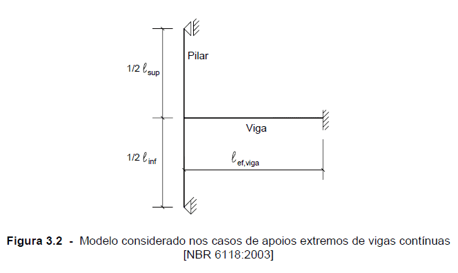
When exact values of the requesting efforts in the structure are not calculated, it is possible to adopt the static form indicated in Figure 2, in order to obtain the moments of the fluss in the extreme supports, such as simplification.
Figure 2 – Model considered in cases of extreme support of continuous beams.
The requesting moments in the upper and lower branches of the pillar are obtained by: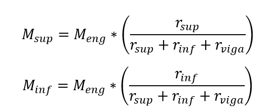
Being, Meng the perfect setting moment in the analyzed tram (end of the beam) of the beam.
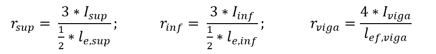
The stiffness coefficients of the upper and lower sections of the column and the beam section are defined by the relationships between moments of inertia and spans, as shown in the following expressions:
 The fletor moment on the beam is determined by the following expression, considering the balance of the node.
The equivalent length of the column can be determined by the expression:
 being that:
lo there the distance between the internal faces of the structural elements, supposedhorizontal, which link the pillar.
h the height of the cross-section of the column, known at the plane of the structure.
l the distance between the axes of the structural elements to which the pillar is linked.
The effective spans of the beams can be calculated by the expression:
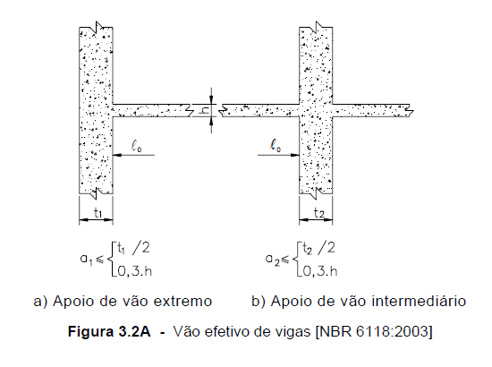
The values of a1 and a2, at each end of the span, can be calculated by the appropriate values of ai, indicated in Figure 3, being:
a1 equal to the lowest value between (t1/2 and 0.3 * h).
a2 equal to the lowest value between (t2/2 and 0.3 * h).
Figure 3 – Go effective beams.
2.3.2 SHAPE ECCENTRICITY
To adjust the position of the structural elements as a function of the architectural design, structural designers need to make the internal or external faces of the beams compatible with those of the pillars that receive them. When this happens the axes of the beams do not pass through the center of gravity of the section of the column (figure 4), thus emerging eccentricities called eccentricities of form (AGUIAR. 2000).
Figure 4 – Eccentricity of shape in pillars.
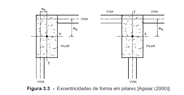
The eccentricities of form, when done the projects and structures of buildings, are not considered in the dimensioning, without the help of computer programs elaborated for this purpose. The fletor moment generated by eccentricities at the level of each floor is leveled by a torque, causing, on each floor, pairs of forces of the same order of magnitude and contrary directions, which cancel out. Computational programs elaborated for structural analysis and dimensioning with crack opening checks and the criteria of the last limit states and displacements with the parameters of the service limits states, take into account these eccentricities of form.
2.3.3 ACCIDENTAL ECCENTRICITY
NBR 6118 (2014) provides for the calculation of an accidental eccentricity (ea), taking into account the situations of local imperfection due to the construction of the pillars, may be by the disintegration of the column axis.
According to NBR 6118 (2014), in the normal reticulated structures, it is admitted that the effect of local imperfections is resolved if the value of the minimum total moment is considered. In the case of oblique composite flexion, the minimum moment value necessarily has to be respected separately in each of the main directions.
2.3.4 SECOND-ORDER ECCENTRICITY
Second-order local effects can be calculated by approximate methods or by the general method. Only the effects of 2nd order for the median slender pillars are considered, using the standard column method with approximate curvature and the standard column with approximate stiffness. The medians represent most of the occurrences in current structures of buildings, and the cases of pillars with slender indexes higher than 90 are unusual.
- Standard pillar method with approximate curvature
When designing columns with λ ≤ 90, with a constant section and symmetrical and constant reinforcement along its axis. This method used only in the case of normal composite flexion. Physical non-linearity is taken for an expression close to curvature in the cross section that expresses the highest bending moment value considering the first and second order moments. The maximum total moment in the pillar, that is, the sum of the 1st order moments and the 2nd order moments, is calculated by the expression:
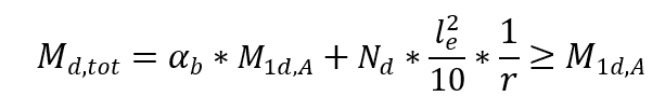
Being that

αb is a coefficient that depends on the distribution of moments in the pillar.
M1d, A the calculation value of the moment of 1st order MA;
h the height of the column section in the analyzed direction;
ν the normal dimensionless force;
fcd the compressive strength of concrete calculation;
M1d, min the 1st minimum order moment.
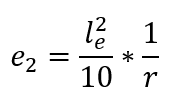
Thus, starting from the second installment of the previous expression, it is inferred that the eccentricity of 2nd order (e2) assumes the following expression:
2.3.5 ECCENTRICITY CAUSED BY FLUENCY
According to NBR 6118 (2014) the eccentricity generated by the fluency of ec concrete must be calculated in pillars with λ > 90, that is, slender and many slender pillars. The effects of fluency on pillars with slenderness indexes lower than 90 are disregarded.
Although the precise analysis of the effects of fluency is a complex work, NBR 6118 brings a simplified expression for the calculation of eccentricity ec, the following: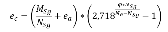 Being that
MSg and Nsg the requesting efforts in the pillar taken from the almost permanent combination;
ea and accidental eccentricity;
φ the fluency coefficient.
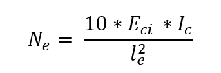
Eci = 5.600⋅ * fck0.5 is the initial elastic modulus of the concrete;
Ic the moment of inertia of the pillar section;
le the equivalent length of the column leg.
The calculated ec eccentricity needs to be added to the eccentricity of the 1st order. Figure 5 shows the eccentricity of the second order.
Figure 5 – Initial and second-order eccentricities in pillars.
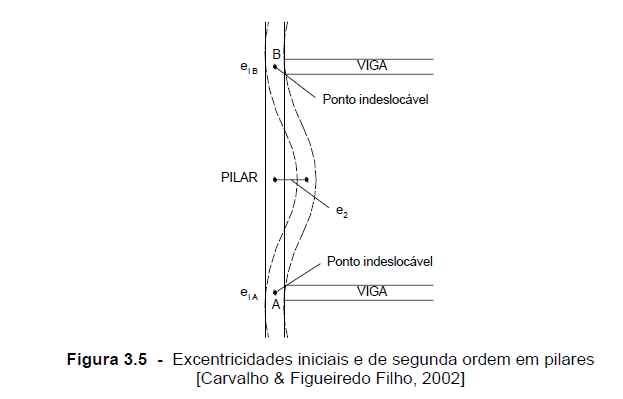
The end sections do not involve the effects of 2nd order and should be considered only in the intermediate section.
2.4 CALCULATION OF LONGITUDINAL ARMATURE WITH ABACUS AID
In the manual dimensioning of the pillars, the abaci are indispensable, because they bring the rapid definition of the reinforcement rate, making it not necessary to apply the theoretical equations of Normal or Oblique Composite Flexion. In addition, abaci allow easy choice of various armor arrangements in the cross section. The Abaci of Venturini and Rodrigues (2000) for Normal and Pine Composite Pinheiro (1994) for Oblique Composite Flexion should be used only in the dimensioning of pillars with concretes of Resistance Group I (fck ≤ 50 MPa), as they were elaborated with some numerical parameters where they do not apply to the concretes of Group II.
2.4.1 NORMAL COMPOSITE BENDING
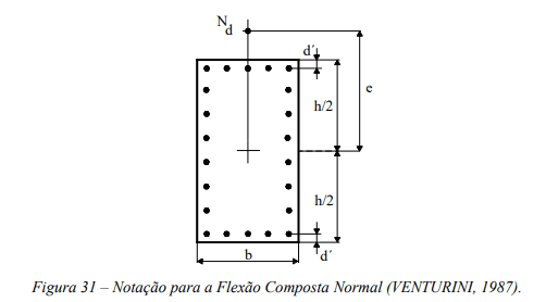
For Venturini and Rodrigues (2000) Normal Composite Flexion, figure 6 shows the notation of the abacus application. The eccentricity (e) is parallel to the distance d ‘, between the center of the corner bar and the face of the section. In general, there is d ‘= c + Φt + Φλ / 2, with c = concrete cover, Φt = stirrup diameter and Φλ = diameter of the longitudinal bar.
Figure 6 – Notation for normal composite flexion.
The equations used for the construction of abaci were pointed out in the publication of Venturini and Rodrigues (2000). The definition of the longitudinal reinforcement is initiated by calculating the dimensional efforts n (ni) and μ (mi). The adimensional value n was defined in the following equation: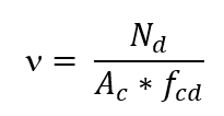
The value of μ, depending on the fletor moment or eccentricity, is:
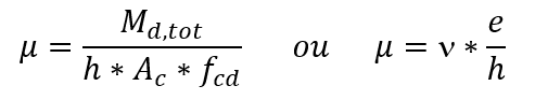 Being
Being
Nd the normal force of calculation;
Ac the area of the cross-section of the pillar;
fcd the calculation strength of the concrete to compression (fck/γc);
Md, tot the total bending moment of calculation;
h the size of the pillar in the direction considered;
and eccentricity in the direction considered.
Once a constructive distribution is chosen for the reinforcement on the column, the abacus to be used is defined, depending on the type of steel and the value of the d’/h ratio. In the abacus, with the pair ν and μ, the mechanical rate ω is obtained. The armature is calculated by the expression:

2.4.2 OBLIQUE COMPOUND FLEXION
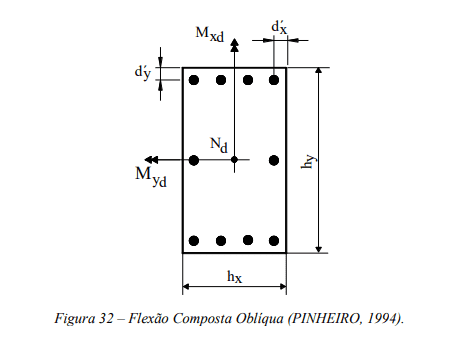
For Pinheiro’s Oblique Composite Flexion (1994) figure 7 shows the notation applied in the use of abaci. The distances d’x and d’y have the same interpretation of d’, however, each in one direction of the pillar.
Figure 7 – Notation for normal composite flexion.
The determination of the reinforcement begins by calculating the dimensional efforts ν and μ, with μ according to the two main directions of the column: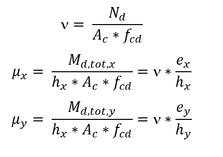 Once a constructive distribution for the reinforcement on the column is chosen, the abacus to be used is defined, depending on the values of the ratios d’x/hx and d’y/hy and the type of steel. In the abacus, with the trio (ν, μx, μy), the mechanical rate ω is obtained. The armature is calculated with the following equation:
2.5 DETAILING OF REINFORCED CONCRETE PILLARS
NBR 6118, 2014 determines that the dimension of the cross-section of the column should not be less than 19 cm. This recommendation aims to avoid unacceptable behavior for structural elements and enable appropriate construction conditions.
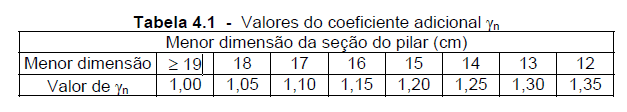
However, for special cases, the smallest size of the column is allowed to be between 19cm and 12cm. For these cases, it is necessary to multiply the final calculation efforts applied in the sizing of the pillars by an additional γn coefficient, according to image 8.
Figure 8 – Values of the additional coefficient γn.
First, the geometric rate of longitudinal reinforcement of the column is defined by the following ratio:
Being that:
As the sum of the cross-sectional areas of the longitudinal bars.
Ac the cross section area of the pillar.
The minimum area of longitudinal reinforcement, depends on the intensity of the request due to the normal strength and strength of the steel, is determined by the following expression: Therefore, the minimum geometric reinforcement rate is equal to 0.4%.
The maximum possible reinforcement area in columns must be 8% of the cross-sectional area, considering the reinforcement overlap in splice regions, that is:
 The minimum diameter of the longitudinal bars shall not be less than 10 mm and shall not exceed 1/8 of the smallest size of the column section.
For proper concreting it is necessary that the concrete has a minimum of space to traverse between the longitudinal reinforcements. Therefore, limitations are imposed on the free spacing between the bars of the longitudinal reinforcement (aL), which must be equal to or greater than the higher of the following values:
- 20 mm;
- The diameter measurement of the bar, beam or sleeve adopted in the seam;
- 1.2 instead the maximum diameter of the aggregate;
The maximum spacing between the axes of the reinforcement bars is also limited, and needs to be less than or equal to twice the smallest size of the column, without exceeding 400mm.
The diameter of the stirrups (φt) in pillars shall not be less than 5 mm or 1/4 of the diameter of the longitudinal bar.
In order to ensure the positioning of the longitudinal reinforcement bars and, in addition, make it impossible to buck the longitudinal bars and use seam reinforcement in the seam regions, maximum spacings between the stirrups (measured in the direction of the column axis) are required, being less than or equal to the lower of the following values:
- 200 mm;
- smaller section dimension;
- 24 φ for CA-25 steel and 12 φ for CA-50 steel, where φ is the diameter of the longitudinal bar;
Where there is a possibility of buckling the bars on the surface, measures should be taken to avoid it.
3. CAD/TQS SOFTWARE MODELING
One of the ways to have a structural calculation detailing, in reinforced concrete, faster and more accurate (with less rounding), is through the use of software, one of them is called TQS, it uses the CAD platform for its operation. With TQS we can obtain the calculations of efforts and arrows in the structure, the dimensions and details of the reinforcements depending on the requests and the plotting of all necessary material, all according to what the professional launched on the drawing platform. The TQS makes all this dimensioning and detailing according to current standards.
TQS systems have resources that make the development of structural projects a highly productive process. From conception to plant issuance, all steps are automated. Its main products are TQS (reinforced and prestressed concrete), Alvest (structural masonry), PREO (precast) and SISEs (geotechnics).
Adapted to the latest regulatory reviews (NBR 6118/2014, NBR 15200:2012, NBR 15.575:2013, NBR 9062:2006, NBR 15812:2010, NBR 15961:2011. Each version of TQS systems are rigorously tested, both operationally and in relation to their results. Also available are educational material for all its products, such as step-by-step TQS, plotting, step-by-step stairs, Alvest step-by-step (TQS, 2020).
3.1 STRUCTURAL RELEASE IN TQS/CAD SOFTWARE
The structure made for analysis was the complete example of the book Structural Project of Reinforced Concrete Buildings, by José Milton de Araújo (2014). For the modeling in the software were launched the pillars, the beams, the slabs, the stairs, the wall loads, sequentially in the order described.
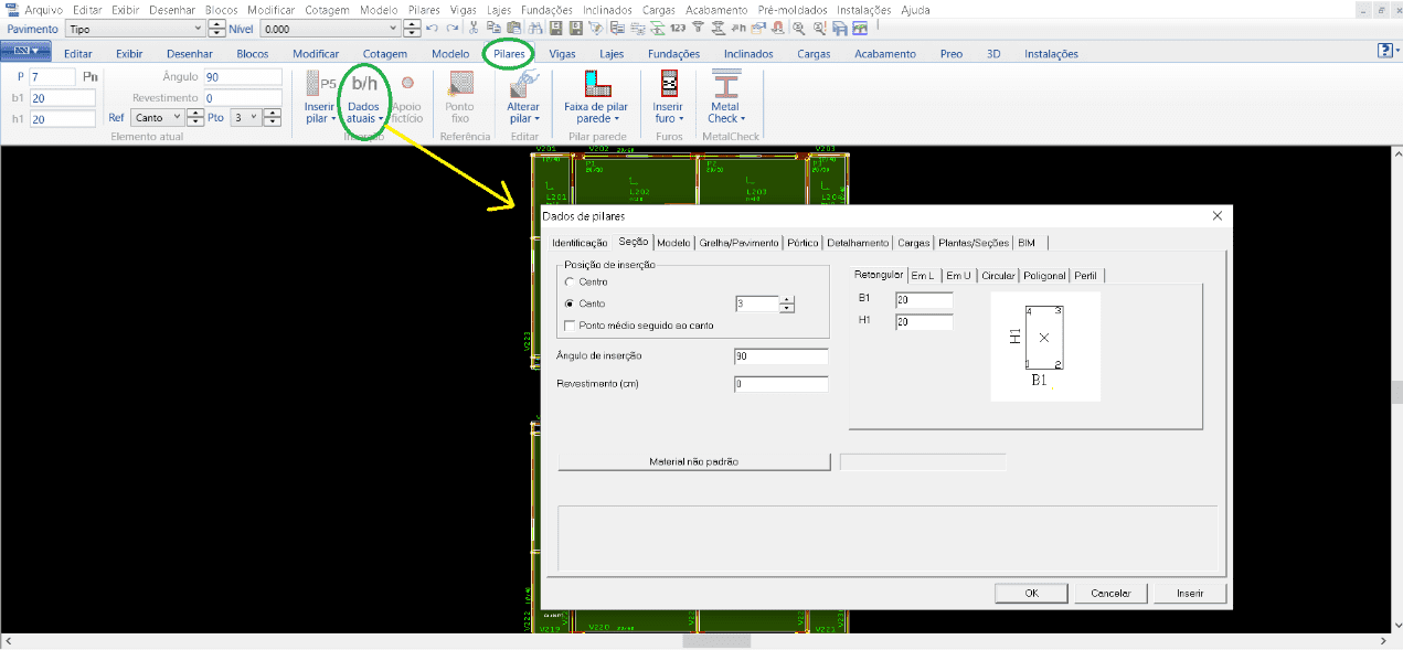
For the pillars, the following steps were followed: After opening the Structural Model, the “Pillars” tab is active, the “Current Data” window must be opened (figure 9), where all the data will appear for insertion of the column, then placing the dimensions, identification number, insertion position, determination where the pillar is born and dies, among other information. At the end of all the relevant editions, then, all necessary pillars are included.
Figure 9 – TQS/CAD window in the “Pillars” tab.
For the construction of beams in CAD/TQS software, the process is as follows:
After defining all the pillars, we move on to the release of the beams. Initially you must activate the “Beams” menu, where all with the following commands are specific to the release of the beams.
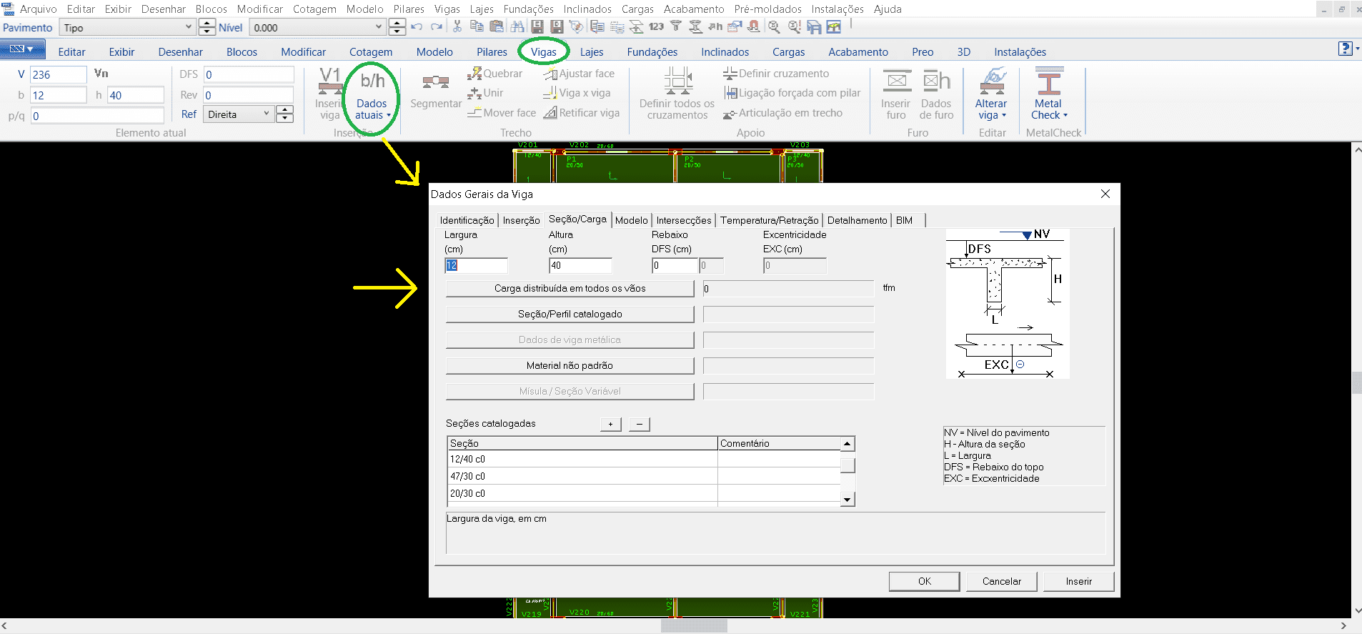
Within the “Beams” tab you must select the command of “Current Data” (figure 10), where you will open a window of the general data of the beams, thus placing all the information necessary for the release of each beam. Information such as the identification number of each beam, its cover, the loads that this beam will act on the pillars, such as the permanent and accidental, its section. After all this detailing process, we can then insert the beam, placing at the starting point then at the end point, usually these insertion points are the vertices of the pillars already inserted previously, repeating the same procedure until placing all the necessary beams.
Figure 10 – TQS/CAD window in the “Beams” tab.
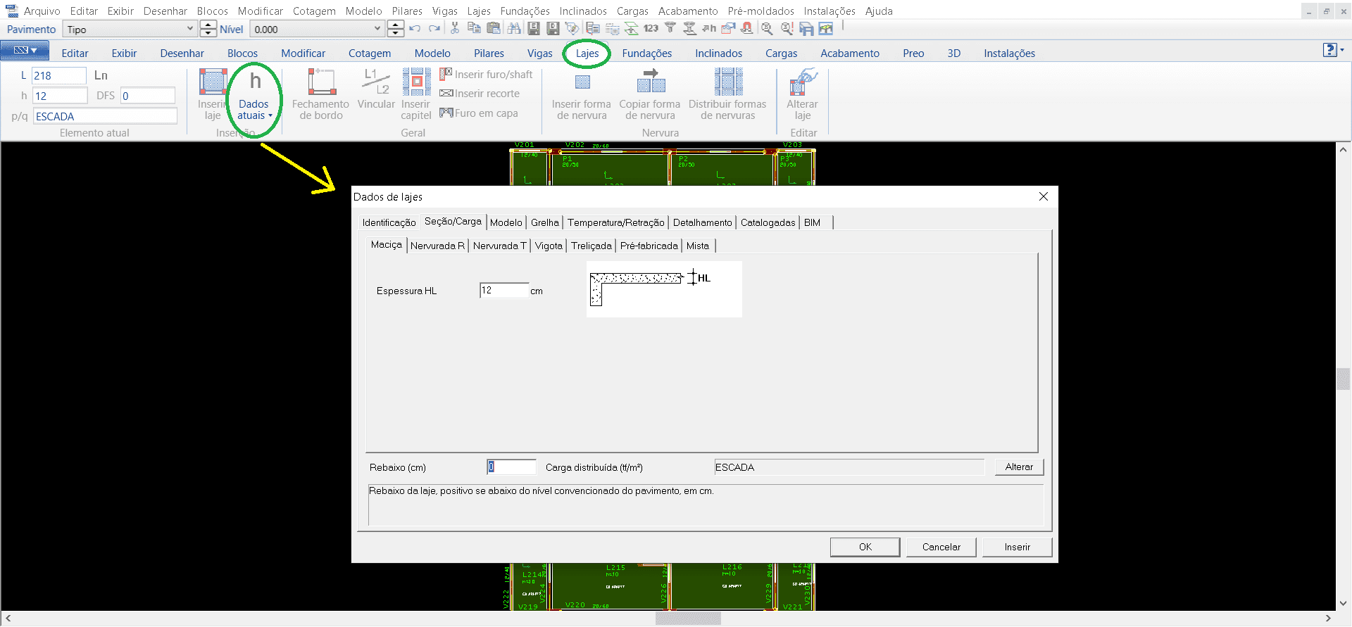
After the beams released we move to the slabs, following the same procedures as the previous ones in the tab “Slabs” selecting “Current data” puts the identification, type of slab and its thickness (image 11).
Figure 11 – TQS/CAD window in the “Slabs” tab.
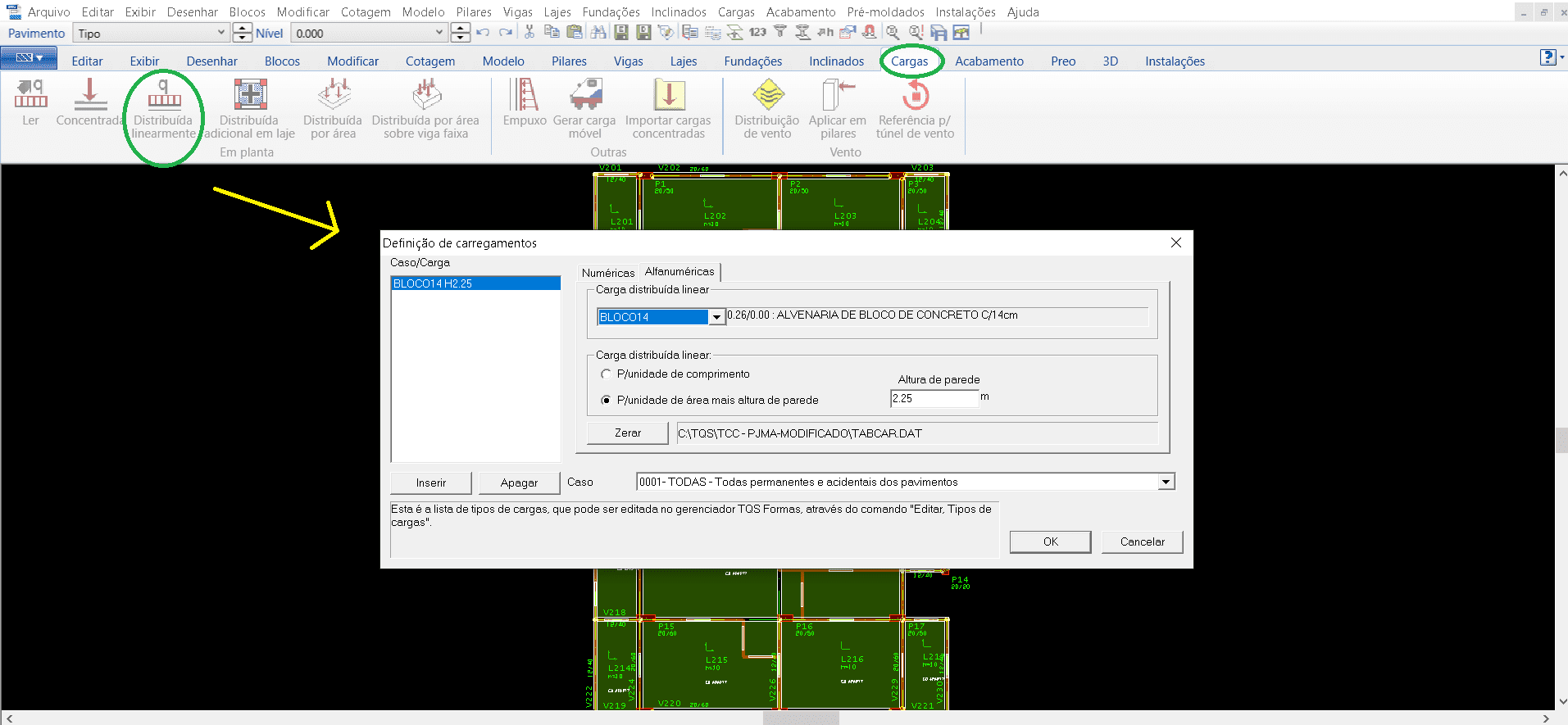
For the posting of wall loads follows the same line of procedures. In the window “Loads” selects the tab “Distributed linearly”, then opening a window for the selection of the type of load, for the modeling in question was inserted block 14 (concrete block masonry 14 cm) and the height of the wall determined (image 12).
Source: Figure 12 – TQS/CAD window in the “Loads” tab.
Thus, when finishing the release of all the necessary elements in the floors, we must save the data defined so far in the “File” menu in the command “Save the structural model”.
Figure 13 – 3D example building, TQS/CAD
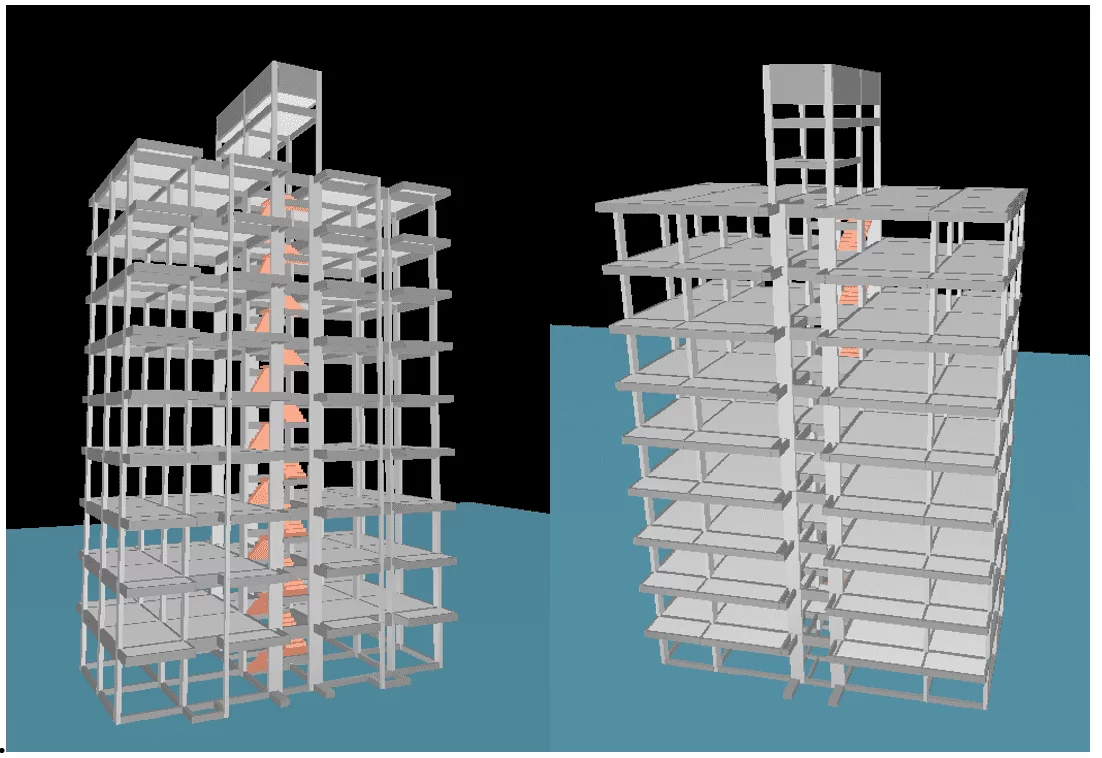
Using the three-dimensional viewer we have the concrete idea of what the example building would look like (figure 13).
The P-Calc application is a TQS calculator that checks reinforced concrete pillars subject to individual oblique composite bending (TQS, 2020).
The main features of P-Calc are:
- Verification of pillars submitted to composite flexion, normal or oblique, in relation to the last limit state of rupture and instability;
- Analysis of pillars with high strength concrete (fck > 50 MPa);
- Normal effort x deflector moment interaction diagram (FCO and FCN);
- Graphical results for stresses and deformations in the section;
- Evaluation of the local effects of 2nd order adopting geometric and physical nonlinearity, according to ABNT NBR 6118;
- Envelomycist of minimal moments;
- Calculation memory in PDF format;
4. PRESENTATION AND ANALYSIS OF RESULTS
This topic presents the comparisons between the references for the elements studied. It was divided into subtopics for the main elements of a structural project. It is emphasized that the references studied were the basis of the project of the book “STRUCTURAL DESIGN OF ARMED CONCRETE BUILDINGS” by JOSÉ MILTON DE ARAÚJO, 3rd edition, modeled, calculated and detailed in the TQS. For the other tests, some elements were compared with other calculation tools such as Pcalc and Bending Abaci for the data of the pillars.
4.1 COMPARATIVE MODELING AND DIMENSIONING – PILAR
After modeling and dimensioning of the pillars, according to topic 3, the main effort, section and steel area were compared between the references studied for the two pillars (P2 and P5) according to the abstract in tables 01 and 02.
Table 1 – Presentation of the results compared to pillar 2
| Elements | Characteristic efforts (tf) | Section (cm x cm) |
Steel area (cm²) |
| Araujo (2014) | 71,4 | 20 x 50 | 6ϕ20 (18,90) |
| TQS | 66,2 | 20 x 50 | 8ϕ20 (25,20) |
| Pcalc* | 71,4 | 20 x 50 | 10ϕ20 (31,50) |
| Pcalc* | 66,2 | 20 x 50 | 10ϕ20 (31,50) |
| Abacus- Normal Flexion* | 71,4 | 20 x 50 | 6ϕ20 (18,90) |
| Abacus- Normal Flexion* | 66,2 | 20 x 50 | 4ϕ20 (12,60) |
*Standard pillar solution with approximate curvature.
Source: Author, 2020.
It can be observed, analyzing the comparisons for the P2 pillar that the araújo dimensioning (2014) in relation to the TQS shows an increase of 33.33% in the steel area, taking into account that Araújo presents a normal force 7.85% higher, already in relation to the PCalc, there was an increase of 66.67%, correlating them with the same load.
It is interesting to note that these same values in relation to the sizing of the standard column with approximate curve using the Normal Flexion Abaci (VENTURINI and RODRIGUES, 2000), was separated into two groups of loads because the modeling done in the TQS differs from Araújo load survey (2014) so we have figures 14 and 15.
Figure 14 – Comparison between TQS x Pcalc x Abaci for Pillar 2
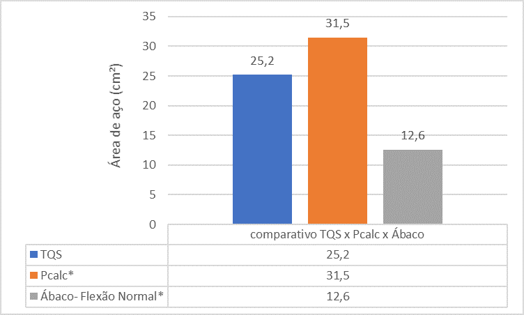
The comparative analysis between the references shows that the steel area of the P2 column found by the TQS tool is smaller than the steel area found by the Pcalc and Abaci. This is due to the fact of the monolithic analysis made in the program.
Figure 15 – Comparison between Araújo (2014) x Pcalc x Abacos for Pilar 2
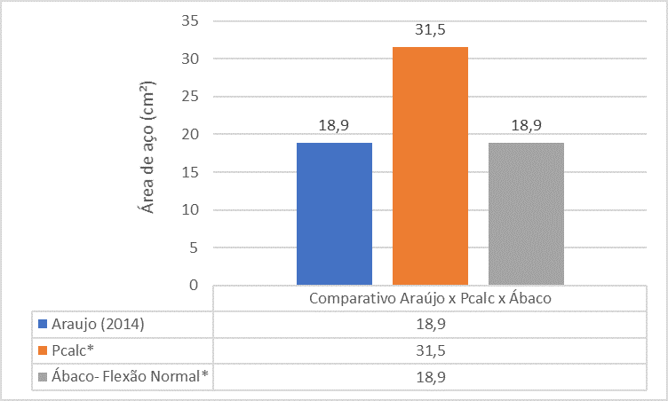
The comparative analysis between the references shows that the steel area of the P2 pillar found by Araújo’s book (2014) is much smaller than the steel area found by The PCalc and Abacus.
The P2 pillar is an end column, intermediate support for beam V202, in the x direction, disregarding these transmitted moments. In the direction y we have beam V 227, this was considered the moments transmitted in the pillar. From this analysis, the perfect setting moment (Meng) was calculus, beam inercia moment (Ivig), beam stiffness coefficient (rvig), moment of inercia of the pillars (Ip), stiffness coefficient of the pillars (rp) and initial moments in the pillars (Mp), from the calculations, the reduced moments are obtained, but divide the big difference between them, were considered zero and size the section in flexo -normal compression in the x direction.
For normal force on the x-axis, we have the index of slenderness (λx) initial eccentricities (eia), accidental eccentricity (eax), minimal eccentricity (e1x,min), initial eccentricity ne intermediary section (eix), second-order eccentricity (e2x) and fluency eccentricity (ecx). The critical session was in the end session, employing the steel area tables the session can be armed with 6 bars of 20 mm, adopting a total steel area equal to 18.85 cm².
Table 2 – Presentation of the results compared to pillar 5
| Elements | Characteristic efforts (tf) | Section (cm x cm) |
Steel area (cm²) |
| Araujo (2014) | 112,2 | 20 x 50 | 10ϕ16 (20,00) |
| TQS | 141,5 | 20 x 50 | 8ϕ25 (40,00) |
| Pcalc* | 112,2 | 20 x 50 | 12ϕ20 (37,80) |
| Pcalc* | 141,5 | 20 x 50 | 12ϕ25 (60,00) |
| Abacus- Normal Flexion* | 112,2 | 20 x 50 | 8ϕ25 (40,00) |
| Abacus- Normal Flexion* | 141,5 | 20 x 50 | 11ϕ25 (55,00) |
*Standard pillar solution with approximate curvature.
Source: Author, 2020.
It can be observed, analyzing the comparisons for the P5 pillar that, araújo’s dimensioning (2014) in relation to the TQS shows a 100% increase in the steel area, taking into account that Araújo has a normal strength 26.11% lower, already in relation to the PCalc, there was an increase of 89% in relation to araújo load, and 50% in relation to the load of the TQS , showing that the higher the increase in load, the greater the divergence of steel areas. It can be said that this divergence is due to the fact of presenting the following error for the resolution of the P5 pillar in the Pcalc, for Araújo (2014) in the last limit state (ELU): The pillar does not pay attention to the verification of the minimum moment. The Pillar with the TQS load in the Pcalc generates the following error ρs = 5.89% > ρs.max = 4.00%.
It is interesting to note that these same values in relation to the sizing of the standard column with approximate curve using the Normal Flexion Abaces (VENTURINI and RODRIGUES, 2000), was separated into two groups of loads because the modeling done in the TQS differs from Araújo’s load survey (2014) so we have figures 16 and 17.
Figure 16 – Comparison between TQS x Pcalc x Abaci for Pillar 5
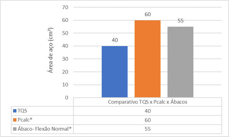
The comparative analysis between the references shows that the steel area of the P5 pillar found by the TQS tool is smaller than the steel area found by the Pcalc and Abaci. This is due to the fact of the monolithic analysis made in the program.
Figure 17 – Comparison between Araújo (2014) x Pcalc x Abacos for Pilar 5
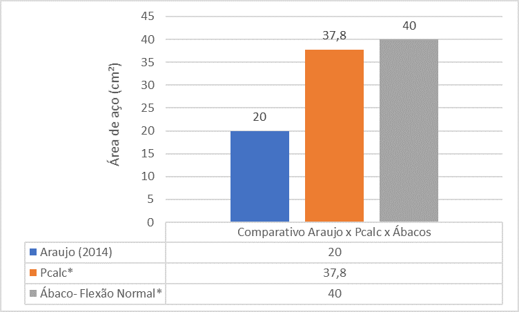
The comparative analysis between the references shows that the steel area of the P5 pillar found by Araújo’s book (2014) is much smaller than the steel area found by The PCalc and Abacus.
The P5 pillar is an intermediate pillar, with the spans and loads of beams V204 and V227, do not differ from each other, so one can disregard the initial moments transmitted by these beams. From this analysis, the calculation was made on the y-axis, because it was the highest slenderness index (λx) found, of eccentricity (ey), given by the sum of first-order eccentricity (e1x), second-order eccentricity (e2x) and eccentricity of fluency (ecy). Using the steel area tables the session can be armed with 10 bars of 16 mm, adopting a total steel area equal to 20.00 cm².
5. CONCLUSION
He observed that the comparison between the methods is important for choosing the best tool for use in the sizing of pillars.
Reproducing the modeling of Araújo’s building in the TQS, a load difference was noticed, and for these loads it is perceived that the TQS tool in default mode is close to the dimensioning for the PCalc and Abaci tool for intermediate pillars.
In araújo end pillars shows a smaller variation of responses in relation to Abaci and PCalc.
Thus, the comparative analysis between the calculation methods is different due to the fact that the monolithic analysis of the structure made in the TQS tool, different from the other methods that presents segmented analysis of the elements with simplified calculation forms.
REFERENCES
ABNT (Associação Brasileira de Normas Técnicas). NBR 6118. Projeto de estruturas de concreto — Procedimento, 1978.
ABNT (Associação Brasileira de Normas Técnicas). NBR 6118. Projeto de estruturas de concreto — Procedimento, 2003.
ABNT (Associação Brasileira de Normas Técnicas). NBR 6118. Projeto de estruturas de concreto — Procedimento, 2014.
ABNT (Associação Brasileira de Normas Técnicas). NBR 15200. Projeto de estruturas de concreto em situação de incêndio. Rio de Janeiro, — Procedimento, 2012.
ABNT (Associação Brasileira de Normas Técnicas). NBR 15575. Edificações habitacionais – Desempenho. Rio de Janeiro, — Procedimento, 2013.
ABNT (Associação Brasileira de Normas Técnicas). NBR 9062. Projeto e execução de estruturas de concreto pré-moldado. Rio de Janeiro, — Procedimento, 2006.
ABNT (Associação Brasileira de Normas Técnicas). NBR 15812. Alvenaria estrutural – Blocos cerâmicos. Rio de Janeiro, — Procedimento, 2010.
ABNT (Associação Brasileira de Normas Técnicas). NBR 15961. Alvenaria estrutural – Blocos de concreto. Rio de Janeiro, — Procedimento, 2011.
AGUIAR, E.A.B. Projeto de pilares de concreto de alto desempenho. Dissertação (Mestrado) – Escola de Engenharia de São Carlos, Universidade de São Paulo, São Carlos, 2000.
ARAUJO, José Milton de. Projeto estrutural de edifícios de concreto armado. 3. ed. Rio Grande: Editora Dunas, 2014.
BASTOS, Paulo S. dos Santos. Fundamentos do Concreto Armado. Universidade Estadual Paulista. Bauru, São Paulo. 2006.
BRANDÃO, A. M. S.; PINHEIRO, L. M. Qualidade e durabilidade das estruturas de concreto armado: aspectos relativos ao projeto. Cadernos de Engenharia de Estruturas. EESC. Universidade de São Paulo. São Carlos, 1999.
CARVALHO, Roberto Chust.; FIGUEIREDO FILHO, Jasson Rodrigues de. Pilares de concreto armado. p.9-25. Notas de aula – Universidade Federal de São Carlos, 2002
FUSCO, P.B. Estruturas de concreto – solicitações normais, editora Guanabara, São Paulo, 1986.
PIANCASTELLI, E. M. Patologia, Recuperação e Reforço de Estruturas de Concreto Armado. Apostila para Curso de Extensão, Ed. Depto. Estruturas da Escola de Engenharia da UFRG, Belo Horizonte, 1997
PINHEIRO, L.M.; BARALDI, L.T.; POREM, M.E. Concreto Armado: Ábacos para flexão oblíqua. São Carlos, Departamento de Engenharia de Estruturas, Escola de Engenharia de São Carlos – USP, 1994.
TQS, Calculadora P-Calc, Pilares de concreto, 2020. Disponível em: <https://www.tqs.com.br/apps/p-calc/ejm1se496l>
TQS, Sobre a TQS, 2020.Disponível em: <https://www.tqs.com.br/about>
VENTURINI, Wilson Sérgio; RODRIGUES, Rogério de Oliveira. Dimensionamento de peças retangulares de concreto armado solicitadas à flexão reta. São Carlos, Department of Structural Engineering, School of Engineering of São Carlos – USP, 1987 (reprinted.2000)
[1] Graduated in Civil Engineering.
[2] Graduating in Civil Engineering.
[3] Master’s degree in Geotechnics and Civil Construction. Graduation in Civil Engineering. Graduation in Agricultural Engineering.
Sent: May, 2020.
Approved: May, 2020.