ORIGINAL ARTICLE
RASI, José Roberto [1], CAUNETTO, Donizete [2], BROETTO, Jonathan Figueiredo [3]
RASI, José Roberto. CAUNETTO, Donizete. BROETTO, Jonathan Figueiredo. Metallic tank for water reserve in Brazil: a study of the partial application of API 650. Revista Científica Multidisciplinar Núcleo do Conhecimento. Year 05, Ed. 05, Vol. 01, pp. 33-62. May 2020. ISSN: 2448-0959, Access link: https://www.nucleodoconhecimento.com.br/civil-engineering/metallic-tank
SUMMARY
With the growing demand for water reserve and the lack of technical standards for metal reservoirs in Brazil, several reservoir manufacturers have partially used api 650 for sizing and verifying these reservoirs. In this work, studies were carried out to verify the partial and integral application of API 650, method 1 foot, through the dimensioning of 7 metal tanks with the same volume as a function of different height/diameter (H/D) ratios. It analyzes the circumferential stresses in both cases and sizing provided for in API 650 and determines the most economical height/diameter ratios for water storage.
Keywords: Metallic tank, API 650 standard, sizing, optimization.
1. INTRODUCTION
Cylindrical tanks are structures commonly used for the storage of water, industrial waste, petrochemical waste, oils, grains and etc. (HECKE, 2010).
According to Barros (2010), they are heavy boiler equipment, subject to approximately atmospheric pressure, usually in the range of 0 to 0.5 psi and intended mainly for the storage of oil and its derivatives.
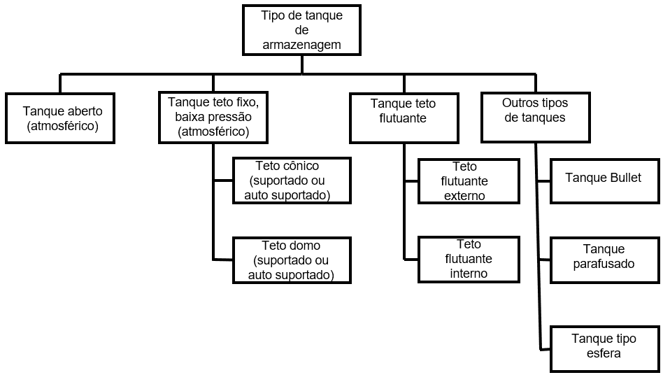
Roncetti (2011) states that there was an increase in the demand for storage of liquid bulk in various economic activities and also the increase in demand for intermediate activities such as sanitation, waste treatment, refrigeration and other manufacturing processes, where it is necessary to stock liquid graneis. Figure 1 illustrates the various types of storage tanks that are commonly used by industries (KUAN, 2009).
Figure 1 – Storage tank types.
The design and construction of atmospheric cylindrical tanks involves a series of special care and requires the knowledge of technical and material standards suitable for each type of application, because failures in these equipmentcan cause great financial losses or even loss of life (NUNES, 2013).
In Brazil, there is a standard for the construction of these equipments. The NBR 7821 standard – Welded Tanks for Storage of Petroleum and Derivatives – published by the Brazilian Association of Technical Standards (ABNT). However, the most widely used standard in industries in general is the American Regulatory Standard API 650 – Welded Steel Tanks for Oil Storage – of the American Petroleum Institute (API), both intended for the reserve of oil and derivatives (SATO, 2015).
According to Barros (2010), API 650 covers specifications on material, design, manufacture, assembly and testing of vertical, cylindrical, unburied storage tanks, with the top closed or open, welded construction, with various dimensions and capacities, for non-refrigerated service, with maximum design temperature of 260º C and approximately atmospheric internal pressure (not exceeding 2.5 psig).
According to Azzumi and Guzey (2015), in accordance with API 650, the three methods for determining the reservoir thickness of cylindrical steel storage tanks designed in accordance with API 650 are:
The one foot method (1FM – one foot method), the variable design point method (VDM), and linear analysis. We compared the shell designs based on these three methods for different tank properties: diameter, height and tension allowed.
The one foot method (1FM), which is based on ” membrane theory ”. The required thickness of the peel plate for each peel stroke is calculated using the circumferential stress at a point of 0.3 m (1 foot) above the horizontal seam of the lower weld of the casserole ferrule due to the hydrostatic pressure of the stored liquid. The 1FM is successfully used for most tanks. However, 1FM-based projects can become conservative and cost prohibitive for larger diameter tanks. Therefore, API 650 limits the applicability of this method to tanks up to 61 m (200 ft) in diameter.
The second method for calculating the required thickness of the shell plate is the variable design point (VDM) method which is also based on “membrane theory”. The VDM was proposed by Zick and McGrath in 1968 and later adopted by API 650 as a refined method to calculate the required thickness of the hull plate, especially for tanks over 61 m (200 ft) in diameter. The VDM takes into account the restriction provided by the tank bottom plates for the first run of the ferrule and the restriction provided by each lower ferrule for the upper ferrule path. The VDM uses a variable distance instead of fixed distance of 0.3 m (1 foot), as used in 1FM, above the circumferential weld (seam) for each runof run, to calculate the maximum circumferential stress due to hydrostatic pressure.
The third method provided in API 650 is the calculation of shell thickness using linear analysis. In this approach, the boundary conditions for the analysis should be a plastic moment related to plate yield under the shell and radial movement totally restricted to the bottom of the shell. API 650 does not describe a specific linear analysis method. In this study, we developed a new method using fine bark theory to perform a linear analysis of the thickness of the calculus bark. In this method, we are using exact rigidity – flexibility relationships and exact functions of the form originating from the so-called ”short shell’ solution of the equations that govern from the fine elastic peel theory.
There was little literary information for calculating a metallic reservoir for water reserve and the lack of specific technical standards for welded tanks for water storage in Brazil.
Due to the lack of a specific technical standard, it has been used as a calculation parameter for metal reservoirs intended for water reserve, API 650 in its entirety or only partially, specifically with regard to the determination of thicknesses of the water’s coasts and permissible stresses, since the safety criteria for fires and explosions of the stored material would not apply to water.
2. MATERIAL AND METHOD
The main objective of this work is to verify the design of open metal tanks, homeless, with the same volume and different H/D, according to API 650, by the one foot method (1FM), in two stages, the first considering only the thicknesses calculated by the equation described in item 5.6.3.2 of that standard;
Where: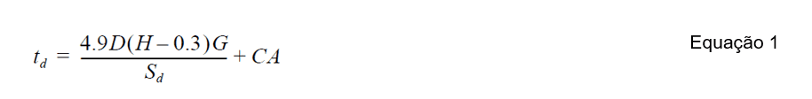
td = design thickness, in mm;
D = nominal diameter of the tank, in m;
H = liquid design level, in m;
G = specific liquid weight in the case of water: 1;
AC = corrosion overthickness, specified by the buyer, in mm;
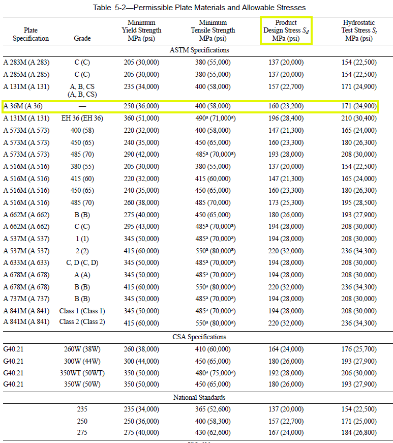
Sd = permissible voltage (table 5-2 API 650), in Mpa.
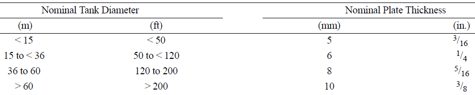
And in the second stage, in addition to the thickness check calculated by Equation 1, the minimum thicknesses are also adopted, as described in item 5.6.1.1 and shown in table 1.
Table 1 – Minimum strand thicknesses
As acomplementary objective, to determine the H/D ratio range that is the most economically viable, with the lowest weight of construction of the welded tank.
The criterion for determining the relationship between the height (H) and diameter (D) of the models is the reservoir volume, kept constant, with 660.00 m³ and maximum diameter less than 15.00 m according to item 5.6.1.1 – API 650, shown in table 1. As a result, for the constant volume (V0) and considered the ratios height / diameter (H/D) between 0.25 and 4.0.
Defined: H = cylinder height; D = diameter and V= volume =
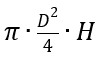
The dimensions of the diameters, heights and proportions between them are described in Table 2 and Figure 2.
Table 2 – Height / Diameter ratios to constant volume of 660.00 m³
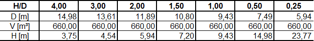
Figure 2 – Geometric models of cylindrical reservoirs studied
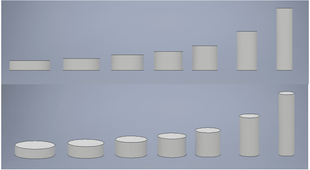
Source: The author himselfThe steel used is ASTM A36, characterized by a modulus of elasticity (E) equal to 205,000 Mpa, Poisson coefficient (μ) equal to 0.30, density (γ) of 77,000 N/mm³, flow voltage fy = 250.00 Mpa and last fu stress = 400.00 Mpa. According to API 650 table 5-2 Permissible Plate Materials and Allowable Stresses, the permissible stress for ASTM A36 steel is 160.00 Mpa (table 3).
Table 3 – Permitted flat materials and permissible stresses
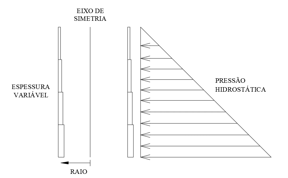
The thickness of the plates of the reservoir body are considered variable along the height of the reservoir (figure 3).
Figure 3 – Plate variation along the height of the reservoir
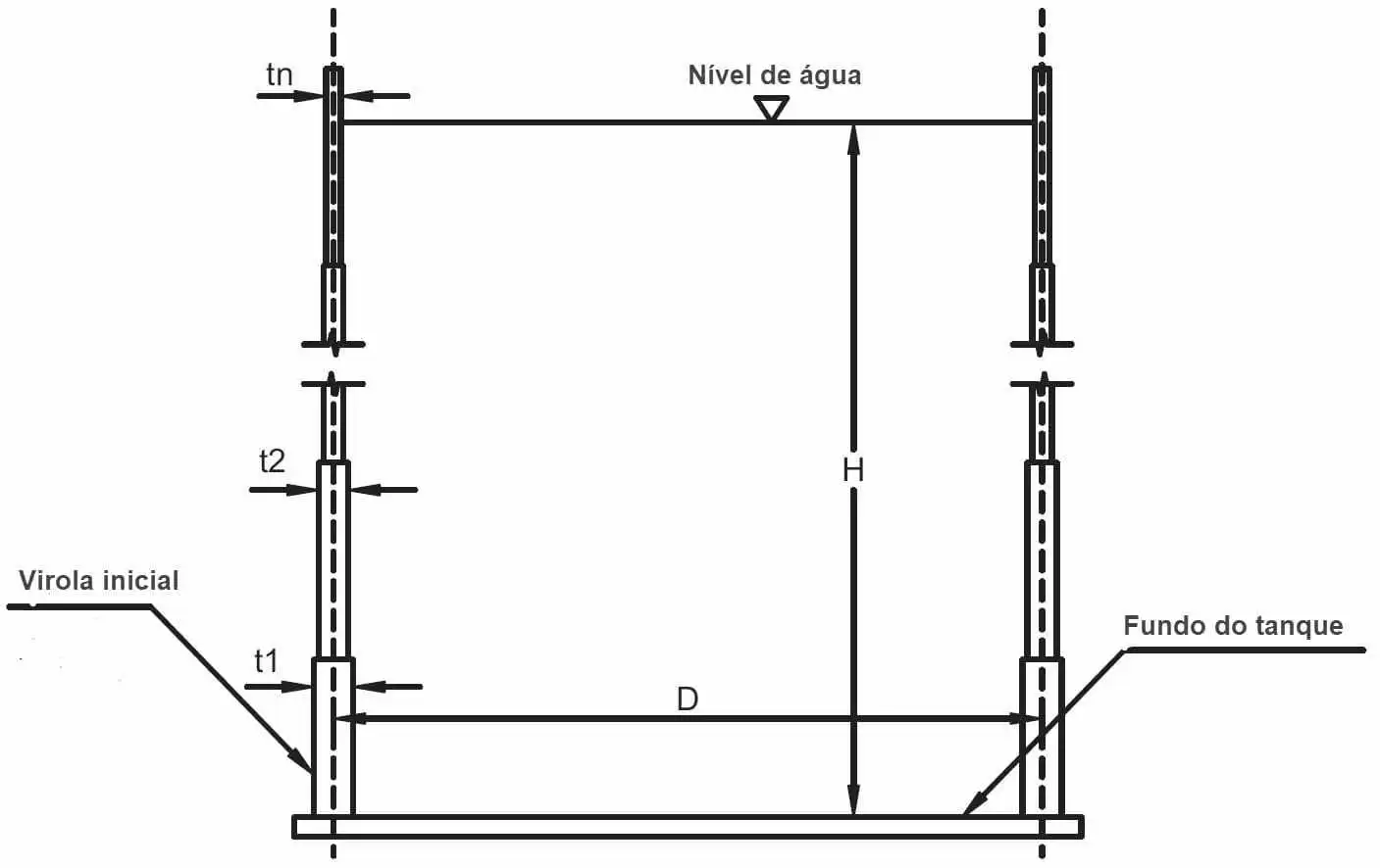
Considering the absence of friction due to the stored material (water), the condition of the reservoir is completely full, the non-application of wind and the conditions of the thickness es of the plates of the bodies of the reservoirs (virolas), results only 1(one) case of analysis (Figure 4):
Figure 4 – Tank with liquid and variable wall thickness over height
The calculation flow of the thicknesses of the warhands of the welded tanks minses the diagram shown in Figure 5.
Figure 5 – Flow diagram of the calculation of the thicknesses of the watercans of the tanks
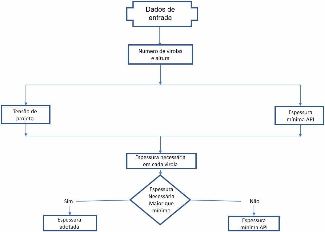
Source: The authorhimself
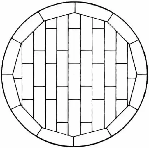
The weights of the 7 tanks proposed in this work were calculated in two stages. The first step calculated the weight of the reservoir funds, considering funds with annular plates (Figure 6), according to item 5.4.1 of API 650 (Botton Plates), which prescribes the minimum thickness of 6.00 mm (1/4). Plate overlap of around 2.26% was considered in the weight of the reservoir funds.
Figure 6 – Typical arrangement of bottom plates with annular plates.
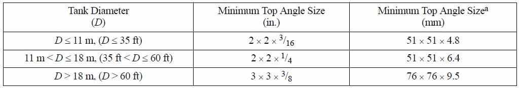
The weights of the upper edge reinforcement angle profiles were also considered, as specified in Table 4 prescribed in API 650 item 5.1.5.9 – Roof and Top-Angle Joints”, superimposed on the last ring (ferrule) of the side, with horizontal flap facing the external side of the tank.
Table 4 -Reinforcement of upper edge of the side.
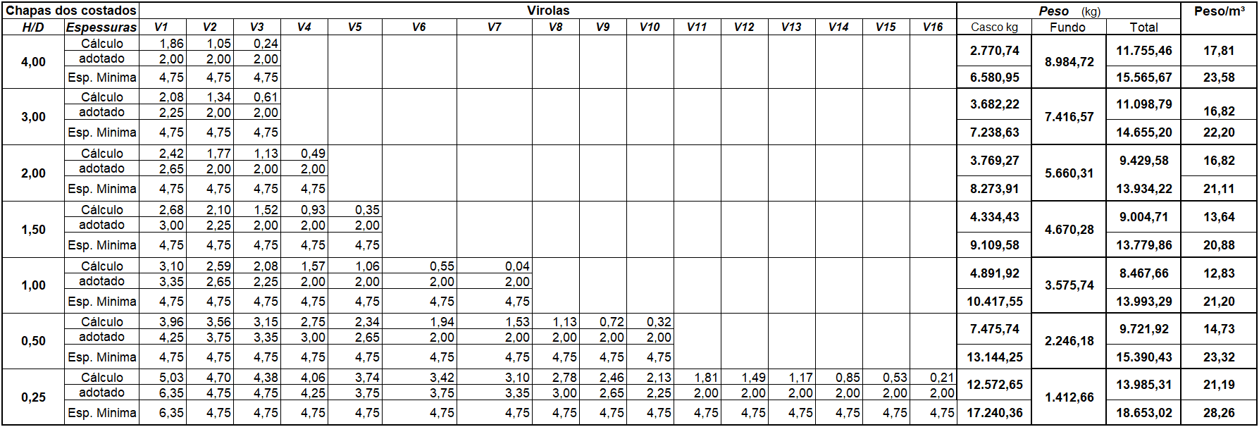
The weight of the strands was determined after determining the thickness of each plate that composes the watercans of the tanks for each H/D ratio, considering the thicknesses calculated only with equation 1 and the thicknesses considering the minimum thicknesses prescribed by API 650 (Table 5). The one-foot (1FM) method was used, with welding efficiency of 1.00 (100%) and without consideration of corrosion overthickness and the forces resulting from the action of winds were not applied. The thicknesses used for the dimensioning of the virolas were (in millimeters): 2.00; 2,25; 2,65; 3,00; 3,35; 3,75; 4,25; 4.75 and 6.35, all with a width of 1,500.00 mm.
Table 5 – Thickness of the plate of the strands and weights of the studied tanks.
3. FINITE ELEMENT METHOD ANALYSIS
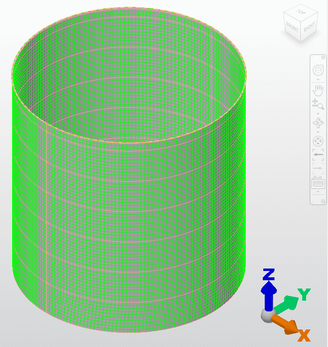
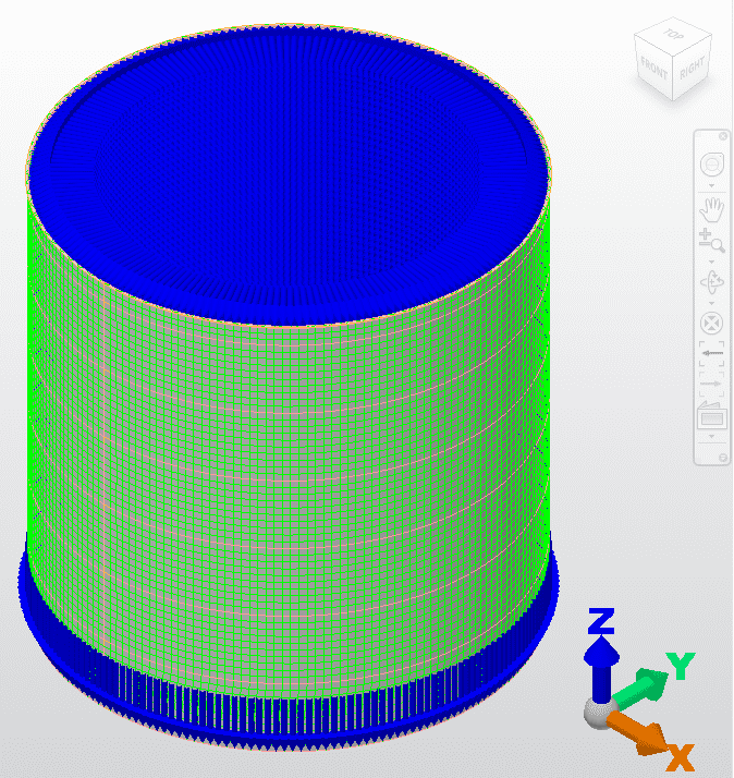
For the analysis by the finite element method (MEF) of the 7 tanks with a capacity of 660.00 m³ and dimensions described in Table 2, the AUTODESK SIMULATION MECHANICAL 2018 software was used, with discretization of the mesh at 150 x 150 mm (Figures 7 and 8 ).
Figure 7 – Discretization of the H/D reservoir 1.00 – diameter and height 9.43m.
fFigure 8 – Application of water loading reservoir H/D 1.00
4. RESULTS
Follow the results of the analysis using the finite element methods – MEF, of the 7 proposed tanks, using the AUTODESK SIMULATION MECHANICAL 2018 software
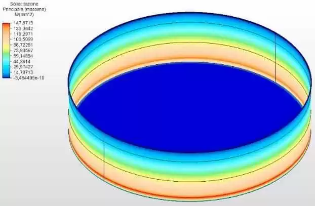
4.1 TANK H/D = 4.00 – DIAMETER14.98 M AND HEIGHT 3.75 M
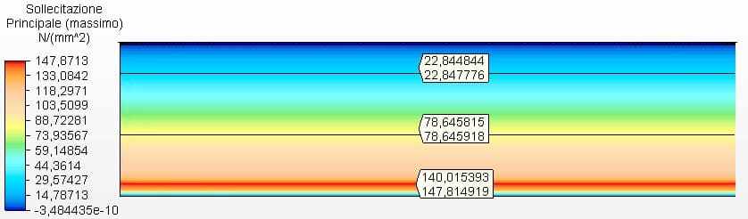
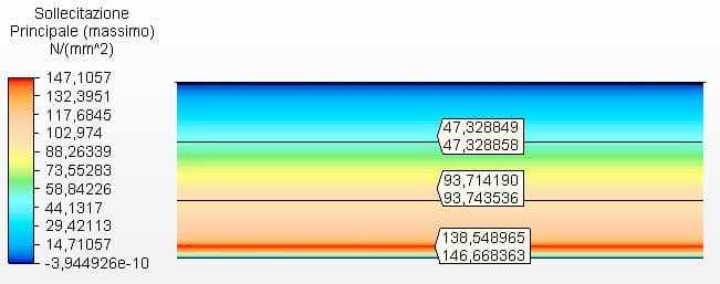
Figures 9 and 10 show the circumferential stresses with the tank thicknesses calculated according to Equation 1 and assumed as 2.00 mm. The maximum vibe 1 voltage was 147.81 Mpa, lower than the permissible stress of ASTM A36 steel of 160.00 Mpa, according to table 5-2 of API 650.
Figure 9 – Circumferential stresses H/D 4.00 in 3D – calculated thicknesses
Source: The author himself
Figure 10 – Circumferential stresses H/D 4.00 in 2D – calculated thicknesses
Source: The authorhimself
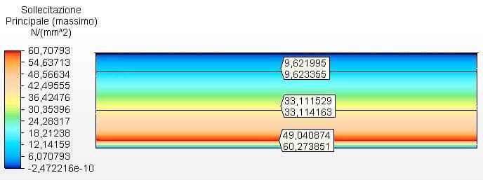
Figure 11 shows the circumferential stresses with the tank thicknesses calculated according to the minimum thicknesses of API 650, in case 4.75 mm. Maximum voltage was 60.27 MPa.
Figure 11 – Circumferential stresses H/D 4.00 in 2D- minimas thicknesses
Source: The author himself
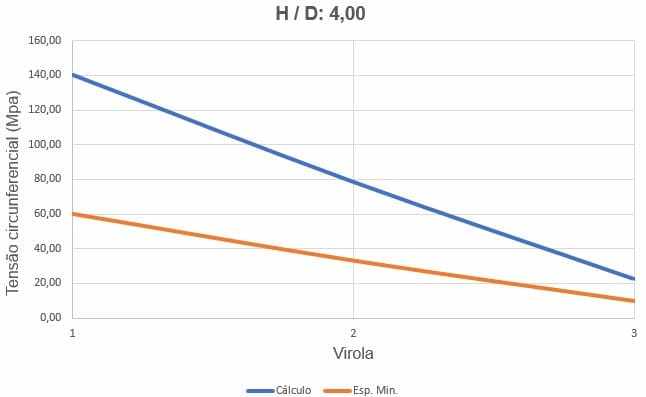
Figure 12 shows the curves of circumferential stresses, depending on the thickness of the ferrules and water loading height.
Figure 12 – Curves of the circumferences of the H/D tank 4.00
4.2 TANK H/D = 3.00 – DIAMETER 13.61 M AND HEIGHT 4.54 M
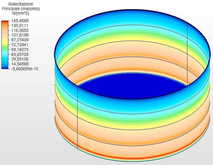
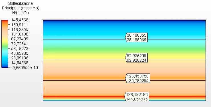
Figures 13 and 14 show the circumferential stresses with the tank thicknesses calculated according to Equation 1 and assumed as ferrule 1 with 2.25 mm and the other with 2.00 mm. The maximum virule 1 voltage was 146.67 Mpa, lower than the permissible stress of ASTM A36 steel of 160.00 Mpa, according to table 5-2 of API 650.
Figure 13 – Circumferential tensions H/D 3.00 in 3D – calculated thicknesses
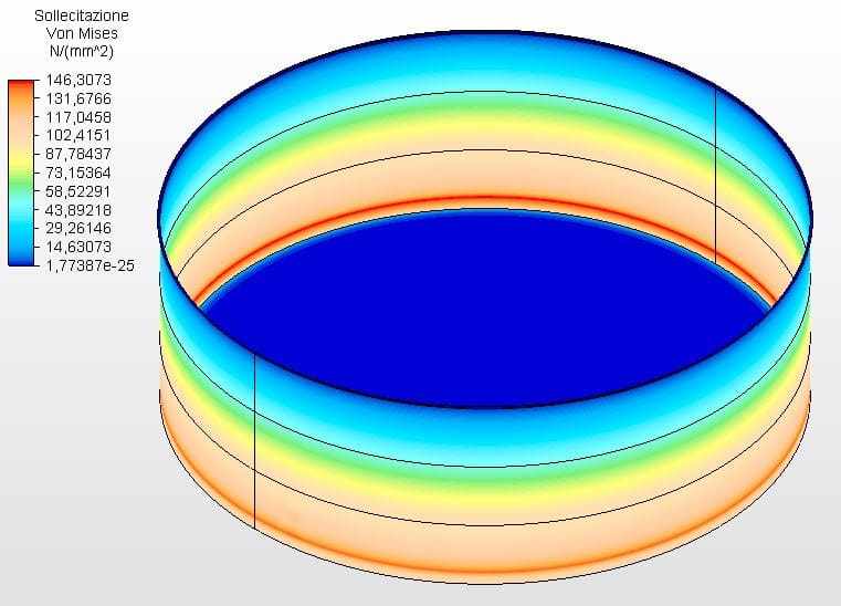
Figure 14 – Circumferential stresses H/D 3.00 in 2D – calculated thicknesses
Source: The author himself
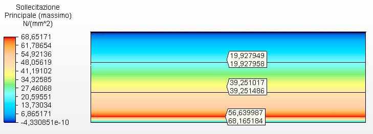
Figure 15 shows the circumferential stresses with the tank thicknesses calculated according to the minimum thicknesses of API 650, in this case 4.75 mm. Maximum voltage was 68.17 MPa.
Figure 15 – Circumferential stresses H/D 3.00 in 2D- minimas thicknesses
Source: The author himself
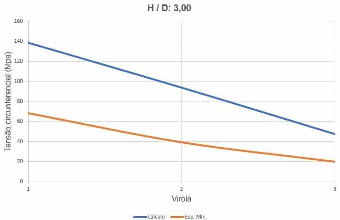
Figure 16 shows the curves of circumferential stresses, depending on the thickness of the ferrules and water loading height.
Figure 16 – Curves of the circumferential stresses of the H/D tank 3.00
4.3 TANK H/D = 2.00 – DIAMETER 11.89 M AND HEIGHT 5.94 M
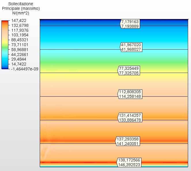
Figures 17 and 18 show the circumferential stresses with the tank thicknesses calculated according to Equation 1 and assumed as ferrule 1 with 2.65 mm and the other with 2.00 mm. The maximum vibe 1 voltage was 144.65 Mpa, lower than the permissible stress of ASTM A36 steel of 160.00 Mpa, according to table 5-2 of API 650.
Figure 17 – Circumferential stresses H/D 2.00 in 3D – calculated thicknesses
Source: The author himself
Figure 18 – Circumferential stresses H/D 2.00 in 2D – calculated thicknesses
Source: The authorhimself
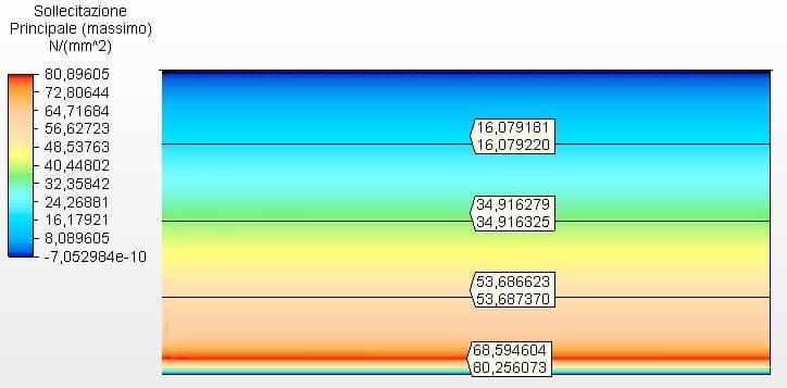
Figure 19 shows the circumferential stresses with the tank thicknesses calculated according to the minimum thicknesses of API 650, in case 4.75 mm. Maximum voltage was 80.26 MPa.
Figure 19 – Circumferential stresses H/D 2.00 in 2D- minimas thicknesses
Source: The author himself
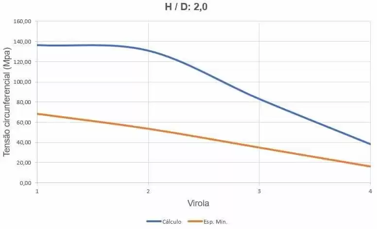
Figure 20 shows the curves of circumferential stresses, depending on the thickness of the ferrules and water loading height.
Figure 20 – Curves of the circumferential stresses of the H/D tank 2.00
4.4 TANK H/D = 1.00 – DIAMETER 9.43 M AND HEIGHT 9.43 M
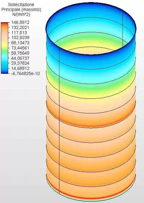
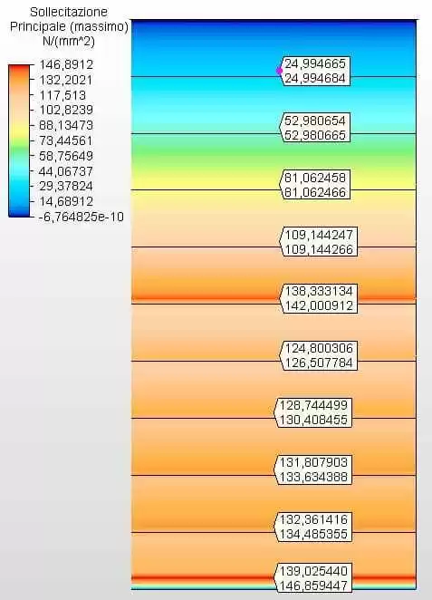
Figures 21 and 22 show the circumferential stresses with the tank thicknesses calculated according to Equation 1 and assumed as ferrule 1 with 3.35 mm, ferrule 2 with 2.65 mm, ferrule 3 with 2.25 mm and the other with 2.00 mm. The maximum vibe 1 voltage was 146.39 Mpa, lower than the permissible stress of ASTM A36 steel of 160.00 Mpa, according to table 5-2 of API 650.
Figure 21 – Circumferential stresses H/D 1.00 in 3D – calculated thicknesses
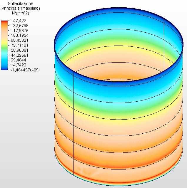
Figure 22 – Circumferential stresses H/D 1.00 in 2D – calculated thicknesses
Source: The author himself
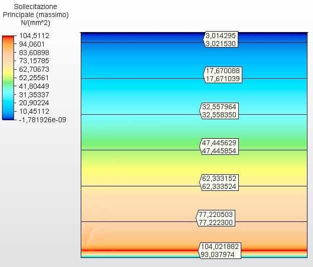
Figure 23 shows the circumferential stresses with the tank thicknesses calculated according to the minimum thicknesses of API 650, in this case 4.75 mm. Maximum voltage was 104.02 MPa.
Figure 23 – Circumferential stresses H/D 1.00 in 2D- minimas thicknesses
Source: The author himself
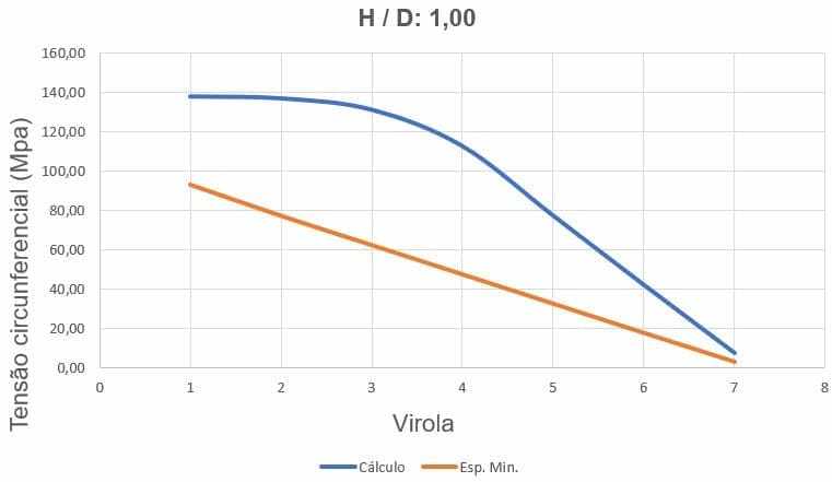
Figure 24 shows the circumferential stress curves, depending on the thickness of the ferrules and water loading height.
Figure 24 – Curves of circumferential stresses of the H/D tank 1.00
4.5 TANK H/D = 0.50 – DIAMETER 7.49 M AND HEIGHT 14.98 M
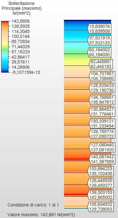
Figures 25 and 26 show the circumferential stresses with the thicknesses of the tank calculated according to Equation 1 and assumed as ferrule 1 with 4.25 mm, ferrule 2 with 3.75 mm, ferrule 3 with 3.35 mm , ferrule 4 with 3.00, ferrule 5 with 2.65 mm and the other with 2.00 mm. The maximum vibe 1 voltage was 146.86 Mpa, lower than the permissible stress of ASTM A36 steel of 160.00 Mpa, according to table 5-2 of API 650.
Figure 25 – Circumferential tensions H/D 0.50 in 3D – calculated thicknesses
Source: The author himself
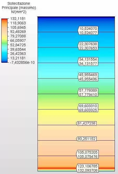
Figure 26 – Circumferential stresses H/D 0.50 in 2D – calculated thicknesses
Source: The authorhimself
Figure 27 shows the circumferential stresses with the tank thicknesses calculated according to the minimum thicknesses of API 650, in case 4.75 mm. Maximum voltage was 132.09 MPa.
Figure 27 – Circumferential tensions H/D 0.50 in 2D- minimas thicknesses
Source: The author himself
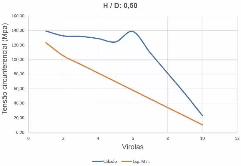
Figure 28 shows the curves of circumferential stresses, depending on the thickness of the ferrules and water loading height.
Figure 28 – Curves of the circumferential stresses of the H/D tank 0.50
4.6 TANK H/D = 0.25 – DIAMETER 5.94 M AND HEIGHT 23.77 M
Figures 29 and 30 show the circumferential stresses with the tank thicknesses calculated according to Equation 1 and assumed as ferrule 1 with 6.35 mm, ferrule 2 with 4.75 mm, ferrule 3 with 4.25 mm , ferrule 4 with 4.25, ferrule 5 with 3.75 mm, ferrule 6 with 3.75 mm, ferrule 7 with 3.35 mm, ferrule 8 with 3.00 mm , ferrule 9 with 2.65 mm, ferrule 10 with 2.25 mm and the other with 2.00 mm. The maximum vibe 1 voltage was 129.72 Mpa, lower than the permissible stress of ASTM A36 steel of 160.00 Mpa, according to table 5-2 of API 650.
Figure 29 – Circumferential stresses H/D 0.25 in 3D – calculated thicknesses
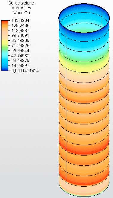
Figure 30 – Circumferential stresses H/D 0.25 in 2D – calculated thicknesses
Source: The author himself
Figure 31 shows the circumferential stresses with the tank thicknesses calculated according to the minimum thicknesses of API 650, in this case 6.35 mm. Maximum voltage was 129.72 MPa.
Figure 31 – Circumferential stresses H/D 0.25 in 2D- minimas thicknesses
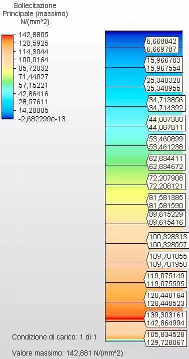
Source: The author himself
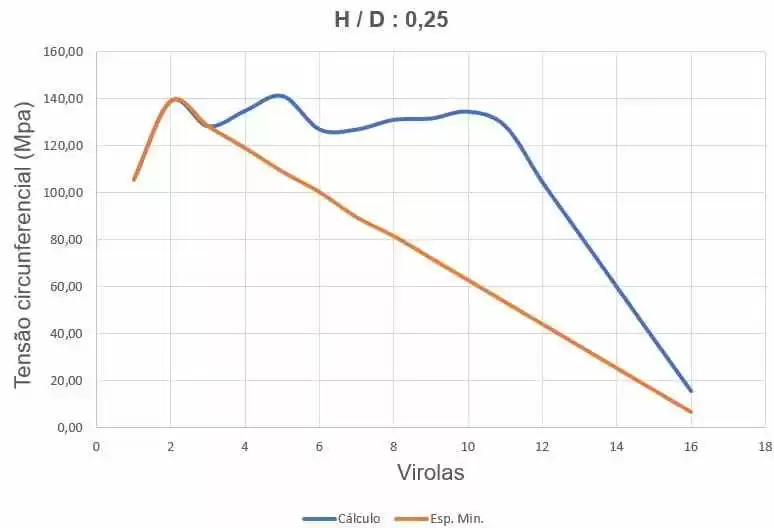
Figure 32 shows the curves of circumferential stresses, depending on the thickness of the ferrules and water loading height.
Figure 32 – Curves of the circumferences of the H/D tank 0.25
4.7 OPTIMAL FULL WEIGHT X H/D BAND CURVE
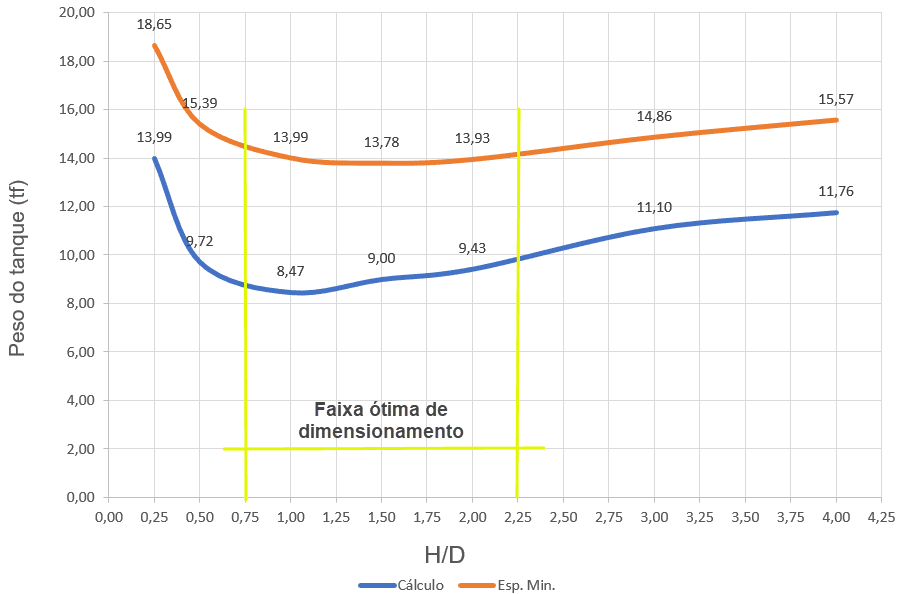
Figure 33 shows the typical weight curves as a function of H/D, for homeless tanks, of variable thicknesses, dimensioned according to the prescription of API 650, with application of Equation 1 (red curve) and minimum thicknesses (blue curve).
The optimal range, for both sizing criteria, is between H/D = 0.75 to H/D = 2.25.
Figure 33 – Typical weight curves of homeless tanks as a function of the H/D ratio.
5. CONCLUSION
From the results presented, it is concluded that it is possible, for water reserve, to establish optimal H/D ratios that point to a minimum weight of the tank, even considering the 2 sizing criteria, i.e. thicknesses with only the application of Equation 1 and thicknesses taking into account the minimum thicknesses prescribed by API 650.
For the dimensioning of metal tanks for water reserve, where the safety criteria for fires and explosions do not apply, the use of sizing with only the thicknesses determined by Equation 1 may be acceptable, because the circumference stresses determined by the MEF (Finite Element Method) were always lower than the permissible stress established in Table 5-2 of API 650.
REFERENCES
AMERICAN PETROLEUM INSTITUTE. API Standard 650: Welded steel tanks for oil storage. 12 th ed. Washington DC, 20013.
ASSOCIAÇÃO BRASILEIRA DE NORMAS TÉCNICAS. NBR 7821 – Tanques soldados para armazenamento de petróleo e derivados. Rio de Janeiro. 1983.
AZZUMI, E., GUZEY, S. Comparison of the shell design methods for cylindrical liquid storage tanks. Engineering Structures 101. 2015.
BARROS, S. M. Tanques de armazenamento. Universidade Petrobras. Rio de Janeiro. 2010.
HECKE, M. B. Elementos finitos aplicados à engenharia de estruturas. Reservatórios cilíndricos e silos metálicos. Universidade Federal do Paraná. Curitiba. 2010.
KUAN, S. Y. Design, Construction and Operation of the Floating Roof Tank. University of Soutthern Queensland. Queensland. 2009.
NUNES, C. P. Uma metodologia de projetos de tanques atmosféricos verticais para armazenamento de petróleo e seus derivados. Monografia. Escola de Engenharia da Universidade Federal do Rio Grande do Sul. Porto Alegre. 2013.
RONCETTI, L. Otimização estrutural e econômica de tanques de armazenamento construídos em aço. Anais do 66º Congresso Anual da Associação Brasileira de Metalurgia e Materiais – ABM. São Paulo. 2011.
SATO, A. K. Projeto de um tanque de armazenamento atmosférico com teto flutuante para estocagem de gasolina. Trabalho de graduação. Faculdade de Engenharia do Campus de Guaratinguetá, UNESP. Guaratinguetá, 2015.
ZICK L.P., MCGRATH R.V. Design of large diameter cylindrical shells. Proc. Division Refining, AMERICAM PETROLEUM INSTITUTE. New York. 1968.
[1] Master’s degree in Structures and Civil Construction; Specialization in Industrial Constructions; Specialization in Environmental Engineering; Specialization in Safety Engineering; Civil Engineer, and Mechanical Operation Engineer.
[2] Specialization in Structural Engineering and Civil Engineering.
[3] Civil Engineer.
Sent: April, 2020.
Approved: May, 2020.