NETO, Alberto Antônio Tuma [1]
ROSA, Daniel de Souza [2]
SOUZA, Ênio Neves de [3]
GARCIA, Fabiano de Aguiar [4]
MEDEIROS NETO, Gracindo da Rocha [5]
NECKER, Helder Sumeck [6]
VALADARES, Otávio César de Paiva [7]
CÂMARA, Patrícia Trabuco [8]
ASCUI, Rogério Roman [9]
NETO, Alberto Antônio Tuma; et.al. Technical analysis of feasibility of deployment of restaurant in a public institution. Multidisciplinary Core scientific journal of knowledge. 07 Edition. 02 year, vol. 02. pp 58-90, October 2017. ISSN: 0959-2448
SUMMARY
The feasibility study enables analyses and evaluations are carried out under the technical point of view, economic and legal and that promotes the selection and recommendation of alternatives for the design of projects. Allows you to check if the program, land, legislation, costs and investments are executables and compatible with the objectives of the organ. It is necessary at this point to perform an estimate of costs, in order to support decision-making for cost benefit analysis, the time limit for the preparation of projects and for the execution of the work, the origin of the resources to carry them out, as the weather forecast budget legislation. Feasibility studies are to elect the venture which best respond to the needs, under the economic and technical aspects, so the need to study all the issues mentioned above. In the technical aspect, must evaluate alternatives for the implementation of the project. Environmental assessment involves the preliminary examination of the environmental impact of the project, in order to promote the perfect appropriateness of work with the environment. The socioeconomic analysis, for your time, includes the examination of the possible harmful effects from improvements and the implementation of the work.
INTRODUCTION
After performing technical analysis, load test on structure, vertical deformation measurement, analysis and repair of structural pathologies solutions, proposed conditions of use, maximum occupancy, structural repair of Pathology found.
This article aims to present proposals for layout and analyze with presentations of technical allowances for decision making to promote reform and/or expansion of the Cafeteria.
In support of this report, visits were carried out at the substation and likely deployment site cafeteria.
Inspecting the State of the building, there are some structural problems, with fissures and cracks in beams; electrical problems with wiring exposed and dry with long time of use.
It turns out that, the place to which it is destined to the cafeteria requires adjustments, because it presents environments with poor ventilation and natural lighting, hydraulic and sanitary problems, low "right foot" (height floor/ceiling) and crossing the stream environments Food and garbage output. In addition, to the adequacy of the cafeteria, for establishment of minimum areas to be made available for operation of a restaurant, it is necessary the demolition and building new masonry walls as well as several tears in existing masonry embed and establishment of paths for electrical wiring.
For strengthening of the problems encountered in the old restaurant, related to the operation of a cafeteria, mentioning the problems encountered in DVISA inspections – Department of health surveillance, where found: absence of health disabled, absence of restaurant openings screen, absence of siphoned drain, insufficient ventilation, absence of HVAC equipment, Absence for sink for washing hands, exposed electrical wiring, absence of exclusive washbasin for utensils, Lamp without protection against fall and explosion of lamps, flooring, wall and ceiling, flat material coating, resistant, waterproof and washable, showing wear, Walls covered in grease, gas pipe with rust, etc.
In order to meet the request of the public administration, technical analysis was addressing project for resettlement of a restaurant, being addressed the relevant situations.
ANALYSIS
CURRENT SITUATION OF THE AREA
At the present time the area destined to the restaurant this open, being used by service provider company in charge of building maintenance.
The building was opened on 28 June 1990, with design by the architect Mario Sandoval Porto, went through cracks and vertical deformations problems causing a Pathological process on the beams and slabs, after laboratory tests and "on the spot" have been proposed corrective actions and restrictions of use and occupation.
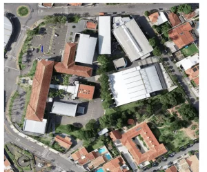
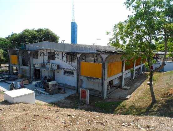
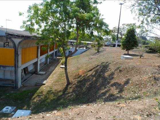
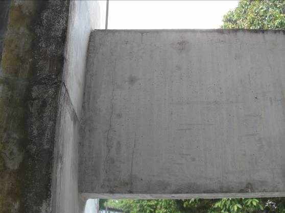
The building is constructed with reinforced concrete structure, divided into three parts by expansion joints offering them solidarity, not seals in .5 masonry time, aluminum frames, Korodur floors, painting in acrylic paint, with two decks, with area = 1,294, 33 m ² and perimeter = 173, 65 m, each deck. The facade is composed in reinforced concrete with structure independent of the main building, as shown in Figure 01 and 02.
According to Sharma (1998), life of a material occurs in the period in which its properties remain above the minimum specified, being of vital importance for the maintenance plans and actual budgets of a work. In this way, performance can be designated as being the in service behaviour of each product, throughout life.
Tan (2001), list as the design flaws related problems the declivity and diameters, associated with the improper location of junction box. Thereby, facilitating the accumulation of solid waste and sewage pains in places generating inappropriate.
DINING AREA
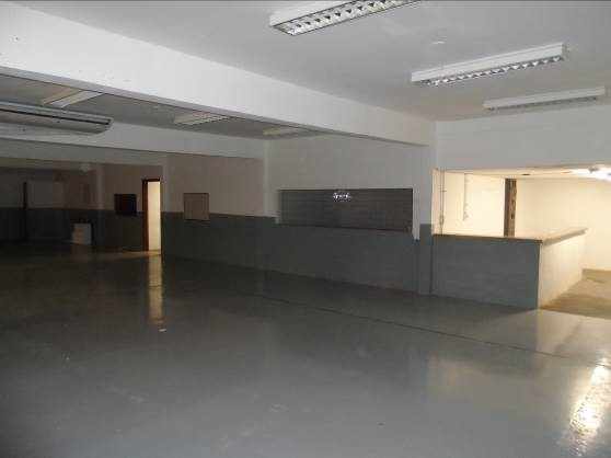
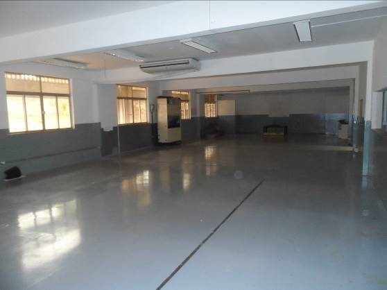
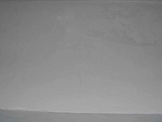
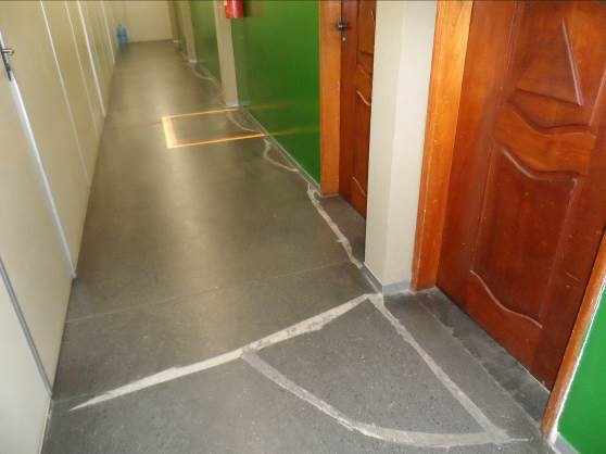
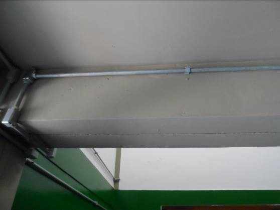
Is in good condition, painted in epoxy floor, walls and ceiling painted in semi-gloss acrylic paint, light fixtures of overlay with reflective plates, according to the Figure 03 and 04. Yet there is a gap of approximately 3 cm in the Middle floor of the Hall. Area = 144.07 m ², Perimeter = 54.20 m, right foot = 2, 88 m.
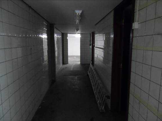
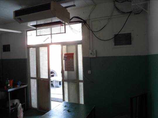
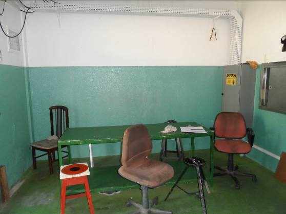
ATTENDANCE
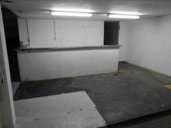
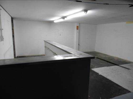
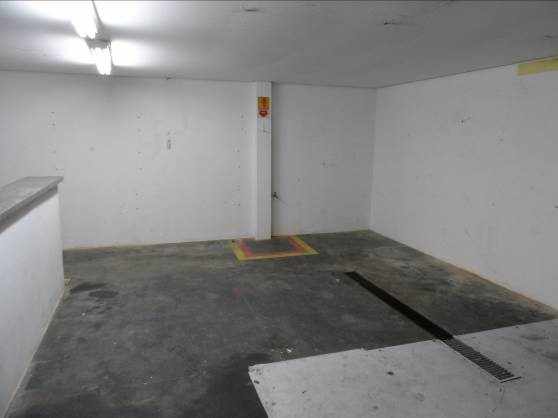
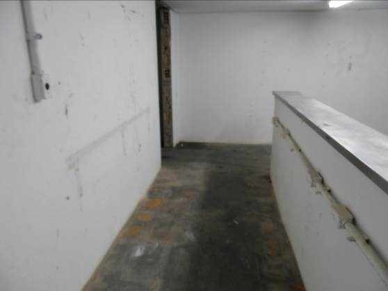
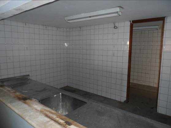
Worn flooring features, stainless steel counter, right foot in 2, 10 m, walls painted in semi-gloss acrylic paint, electrical conduit and apparent outlets, light fixtures of overlay, liner in gypsum, with grate for drainage channel with, as shown in the Figures 5, 6, 7 and 8.
- BAR
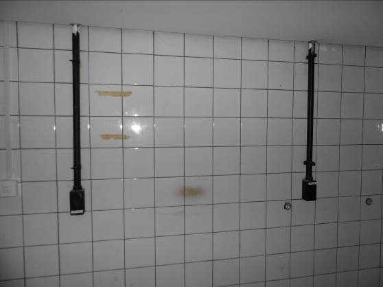
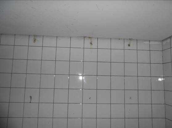
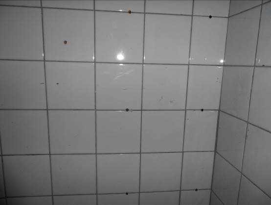
Walls with white tiled flooring damaged with cracks and broken holes, electrical Pipe and fixtures of unprotected, according to figures 9, 10, 11 and 12.
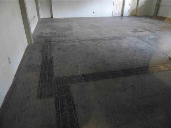
- HALL
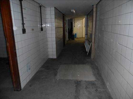
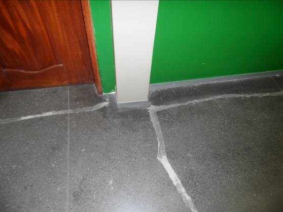
Faulty floor of uniformity, showing a probable junction box within the environment of the restaurant, the wall covering is damaged and has tubing and electrical boxes, shown in figures 13 and 14.
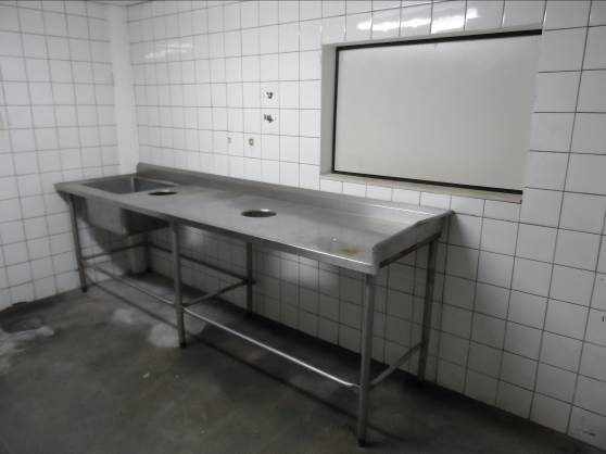
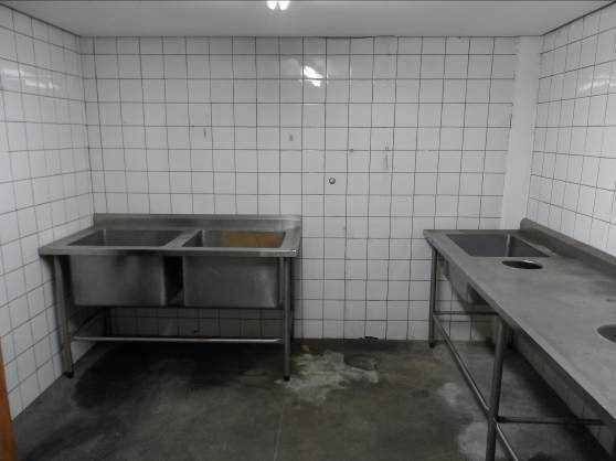
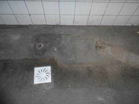
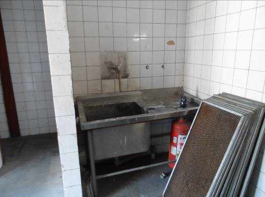
WASHING
Damaged floors with presence of molds, sinkers and siphoned boxes feature return problems odors, inline pipes with leaks, wall coating with cracks and holes, stainless countertops damaged.
- THE CHIEF'S OFFICE
In good condition.
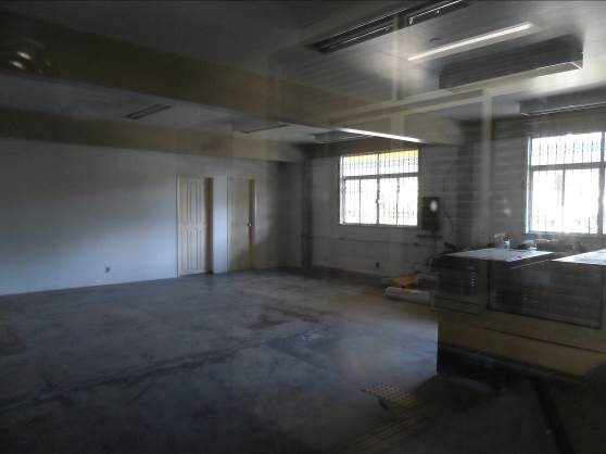
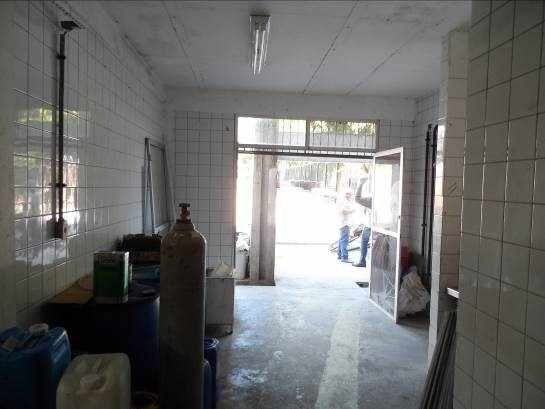
- OLD OFFICE OF BASA
Place holder for work the hot area of the restaurant and must go through adjustments to embed electrical, hydraulic, sanitary pipe and gas. Another issue, adjust holders hoods to prevent load in structure, recomposing grouting and painting, according to the figures 17 and 18.
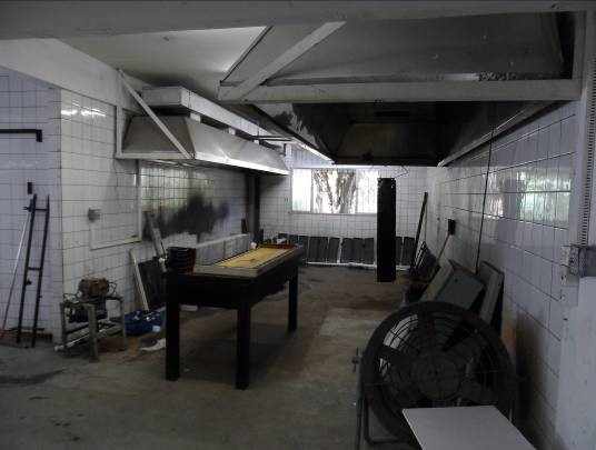
- KITCHEN
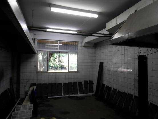
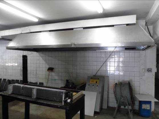
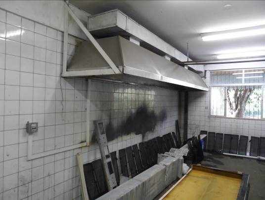
Wall coating completely damaged, hood damaged cooking and ducts installed incorrectly, floor holes and cracks, natural ventilation and lighting below the recommended. The electric, gas and water pipes were executed. Area = 68.10 m ², Perimeter = 34.08 m and right foot of 2, 85 m, shown in figures 19, 20, 21 and 22.
- PRE-PREPARATION
Ceramic coating of walls with holes and cracks being necessary to embed pipes and electrical installations. Problems of lack of sifonada and drainage box damaged. Required demolition of existing water tank.

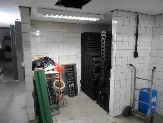
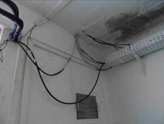
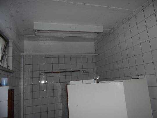
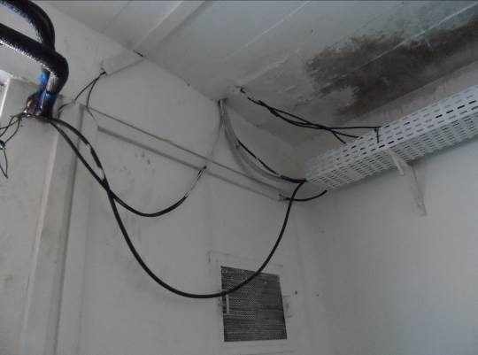
- AIR CONDITIONING
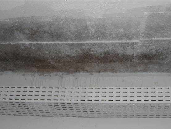
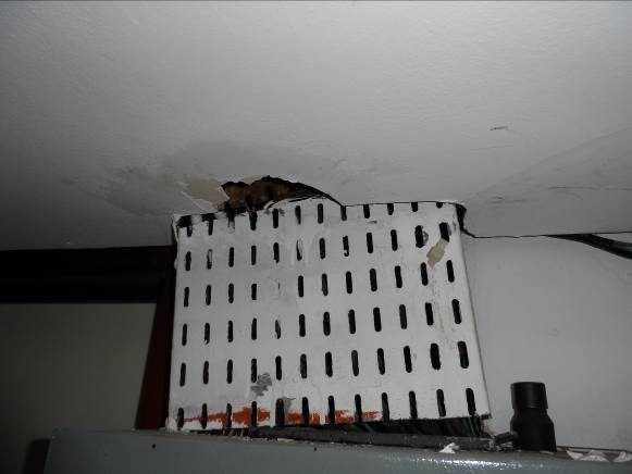
Presents points of infiltration with presence of fungi, exposed electrical wiring, however does not work for general storage of air conditioners, according to presented in figures 25, 26, 27 and 28.

- WASHING
Health links and damaged, makeshift wall cracked and breakdowns, as shown in Figure 29.
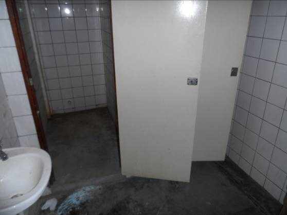
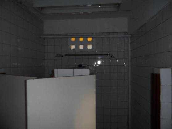
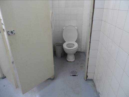
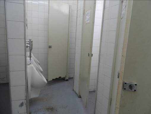
- THE STAFF OF THE RESTAURANT TOILET
Totally damaging requiring total repairs, shown in figures 30, 31, 32 and 33.
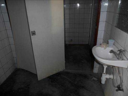
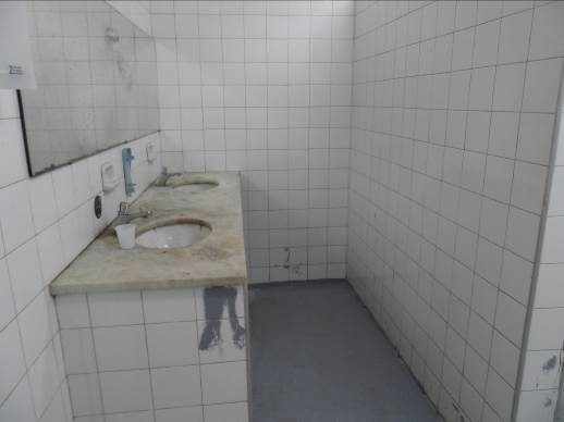
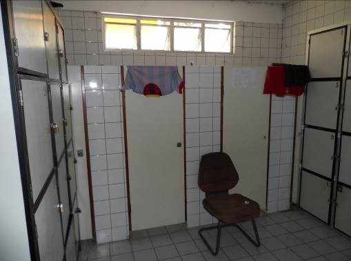
- TOILET RESTAURANT USERS
Used for locker room by employees of maintenance, but requires reform on the ground, sifonada box, doors and hidrossanitárias facilities, according to Figures 34, 35, 36 and 37.
- WASHBASIN
Damaged flooring, wall covering with cracks and holes, showing problems in hidrossanitárias, electric pipe installations, comprising 38 figures, 39, 40 and 41.

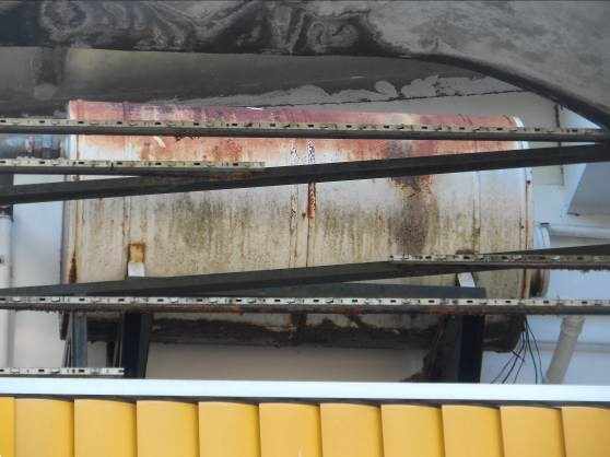
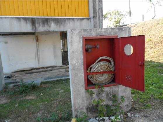
- EXTERNAL AREA
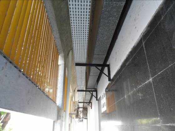
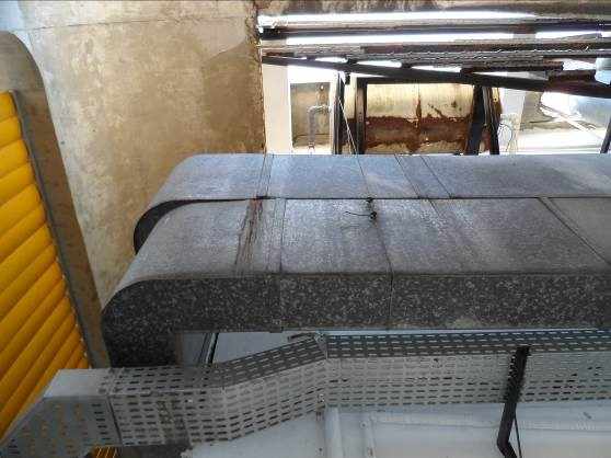
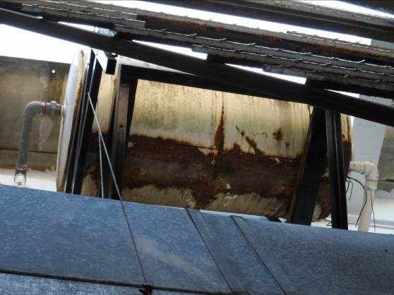
Exhaust ducts installed between the exterior wall and the structure of the façade, angles of support beams. Presents the kitchen exhaust ducts damaged and in violation of the regulations in force, hot water equipment damaged and unused, motors and forced exhaust system without maintenance and fire hydrants and fire fighting system without maintenance, according to the 42 figures, 43, 44, 45, 46, 47 and 48.

PRESENTATION OF TWO LAYOUT SUGGESTIONS
In view of the request of the supervision of Directors – SAD, two Layout suggestions were made for possible deployment of restaurant in the building, please note, that this is a DRAFT, being necessary to the development of more detailed projects and DVISA query for a complete project procedure.
At first, he used the old restaurant area plus the area where work the old Bank agency BASA, resulting an area = 505.59 m ², Perimeter = 96.20 m, the height of floor/ceiling varies from 2, 10 m to 2, 88 m, as Annex A.
In the second, excludes the area for the toilet of the restaurant, and users, it was found that users of the restaurant would use the bathroom from the ground floor which is 12 m from the entrance of the restaurant, however, it is necessary the adequacy to meet the standard of current accessibility (area = 405.87 m ², Perimeter = 99.83 m) as Annex B.
When you examine the State of conservation and durability takes into consideration that the construction date of the Decade of 90, therefore, totaling around 27 years of construction should consider the deterioration of all systems, porting second Tan (2001), from the point of view of durability of the facilities can be a commitment by rodents, corrosion of input boxes, frames, adding, also, exposure to Sun or high temperatures of wires or cables, electrical excess current performance for long periods and excess wiring in the same conduit.
Although it is a draft, sought all subsidies in order to meet the standards and resolutions that cover the installation and operation of restaurants.
Another relevant issue is changing the design of the facade with modification of at least three frames to fit standard lighting and natural ventilation.
CONSTRUCTIVE TECHNICAL IMPLICATIONS And Recommendations
There is a history of diseases and problems related to the building in which although visually strange in test carried out on the local structure of slab bore the burden of project, however decay demonstrating some structural elements being necessary to act in order to maintain the service life and replacement of the constructive characteristics of project.
According to Sharma,
Deterioration analysis allows the trial of a product (or structure), and admit that is considered satisfactory when it characterized a positive relationship between your initial cost, your characteristic curve of decay, your life and your replacement cost or recovery. (Das, 1998, p. 17)
Analyzing the current situation still finds constructive pathologies that require very careful with any change, reform and occupation of the building, but not implying serious problems, monitoring and application of profilaxivas measures.
Thus, despite being possible small interventions in part of the ground floor must act with caution, avoiding any drilling or support installed on joists slabs and pillars to come not accrued load on structural elements.
According to Mathieu,
The cracks are almost always sign or symptom that something wrong is happening with the construction; This problem can be simple in nature, not implying greater care, unless the corrective maintenance, or be the warning of a situation which if not taken care of in time and properly may lead to a critical situation. (Marcelli, 2007, p. 137)
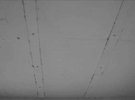
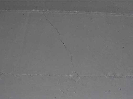
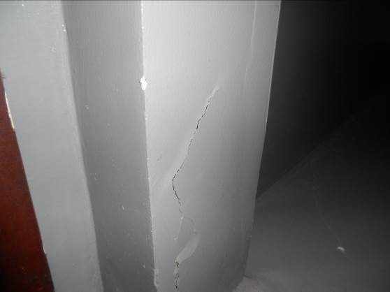
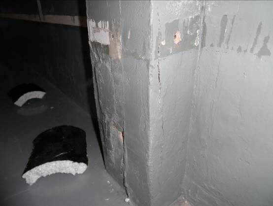
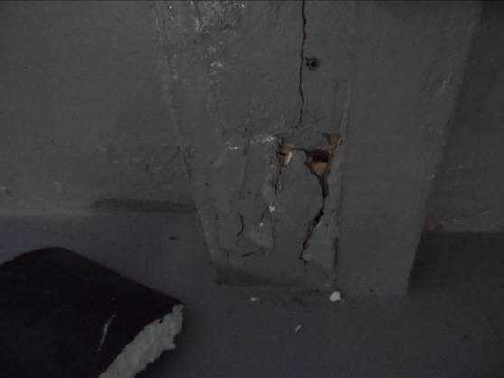
One of the main pathologies found were cracks in beams shear rupture and indicating flexion, as 49 Figures, 50, 51, 58 and 59. Another pathology found is due to oxidation of the steel pillars, according to the figures 52, 55 and 56. In figures 53 and 54, showing cracks in slabs that propagate up to the top floor and Figure 57, one can observe the presence of fungi from infiltration.
According to Sharma (1998),
The record of large structures is fundamental to your maintenance. Based on the registration of the structure it is possible to keep an effective control of routine inspection activities, schedule and register, appropriately, repairs or reinforcements perhaps needed during their lives (Sharma 1998, p. 234).
In this way, it is recommended to reset the damaged structural element with graute application and verification of decrease of cross-sectional and longitudinal reinforcement section. However, the beams indicates the application of structural adhesive epoxy base with steel plates, when the cracks if they demonstrate active.
RECOMMENDATIONS AND TECHNICAL IMPLICATIONS OF ELECTRICITY
Reform: it turns out that the electrical installations are notoriously older and that, therefore, it is not possible to guarantee the reliability and security of existing facilities. It turns out that, in order to ensure the safety of the regulars of this possible cafeteria to be installed, must reform not only property for the electrical installations of the rooms that include the cafeteria, but must also be provided for a reform in the sense lato sensu. Otherwise, there is no way to ensure the full safety of electrical installations.
Power plants: it turns the plants found in the file located at COADM, which, over time, several changes were executed project electric without proper formalization in plants. Good design practices dictate that about that for any modification performed on the same field must also be recorded in the documents so that it is possible to query for support actions retrospectively (as built plans).
Analysis of the Economy of the place: this technical note stick-if only the problems and technical implications found in the dependencies. Technical analysis, as the principle of economy, belongs to the scope of senior management.
Technical Considerations
Substation (Current Situation):
Today, belonging to the group the public sector tariff subgroup, has three 500 KVA transformers, situated in the main substation, in activity, being two active and one inactive, and, in the substation, in inactivity, a 300 KVA transformer located in the substation.
In the midst of the analysis of the capacity of the current active System of main substation to support the new electrical loads to, analyze two hypothetical situations. Such need of analysis represents the fact that there is a need for a detailed study of the amount of electrical loads connected currently through substation and thus determine the reserve capacity of the main substation. Thus, considering only the use of currently existing transformers, follows the analysis of the situations.
Hypothetical situation 1: Current System (500 + 500 KVA) without reservation
The insertion of new electrical charges may result in activation of the third 500 KVA transformer, being oversized, there would be greater this consumption of reactive energy in relation to active power, leading to a low power factor. By way of clarification, in short it is stated that low power factors (excessive reactive energy) are such that the full use of electrical conditioning installation installing new loads to investments that could be avoided if higher values of power factor be achieved. The space occupied by the reactive energy could then be used for the new service loads. It turns out that this "space" occupied by reactive energy carries also in charge in the electric energy consumption if the power factor value is less than 0.92. I quote the article 76 of the normative resolution No. 418, of 23 November 2010:
Art. 76 the power factor of the consumer, for billing purposes, must be verified by distributor through permanent measuring, so mandatory for Group A and optional for Group B.
Quote still the technical standard of Eletrobras, Energy Code MPN Amazons-DC-01/01, effective NDEE-from 04/11/2014:
5.8.7.2 calculation Memory demand likely in kVA and kW (considering a minimum power factor of 0.92); that calculation, the sole responsibility of the technical responsible RT (Technical Manager) for the project as well as the demand factor must include all charges and your more severe regime of continuous operation;
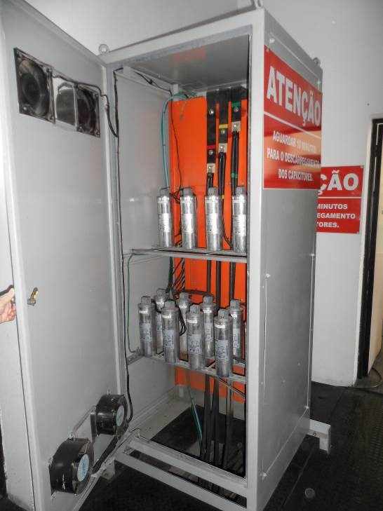
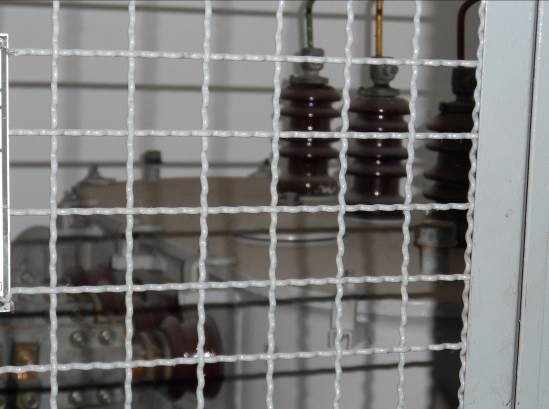
On this requirement and, considering the third activation 500KVA transformer, it is certain that it will be necessary to invest in the Bank of capacitors installed, as pictured below, in the main substation, the company responsible for building maintenance preventive and corrective of the building in order to keep the power factor value of 0.92, to say the least. The analysis of the capacity of the transformers is carried out without prejudice to the analysis of replacement of feeders. The information passed is that these feeders were installed in 1997.
Hypothetical situation 2: Current System (500 + 500 KVA) with reservation
Now the situation in which the two assets 500 KVA transformers are sufficient for the supply of new electric charges. In this case, would not a priori a suitability of the Bank of capacitors located on main substation. The analysis of the capacity of the transformers is carried out without prejudice to the analysis of replacement of feeders. The information passed is that these feeders were installed in 1997 and, therefore, it is not possible to say the perfect integrity of feeder cables.
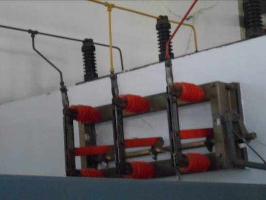
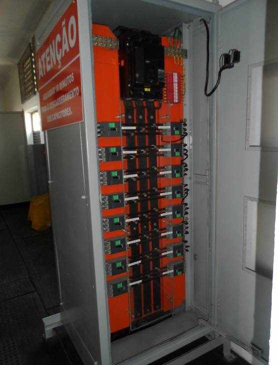
The figure shown in the sequence consists of the general picture. As I mentioned to the feeders, the information received is that the installation of these electrical components was held in 1997. There is no way to specify the degree of integrity of the components and only a detailed study to determine the physical condition of all the integral parts of this system.
Implications and difficulties for deployment
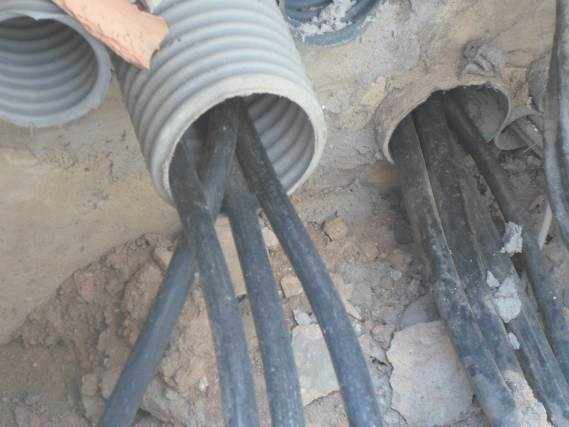
General power: currently there are feeders, cables from the main substation, which meets the equipment installed and in use in the building. It is a relatively deteriorating facility, with circuit breakers with long use and old cables. There is no way to specify the degree of integrity of the components and only a detailed study to determine the physical condition of all the integral parts of this system.
Recommendation: in order to guarantee the new installations, it is recommended that new feeders, cables using existing referrals directly from the main substation, to meet the energy demands that are generated with the addition of new charges electric operation of the cafeteria.
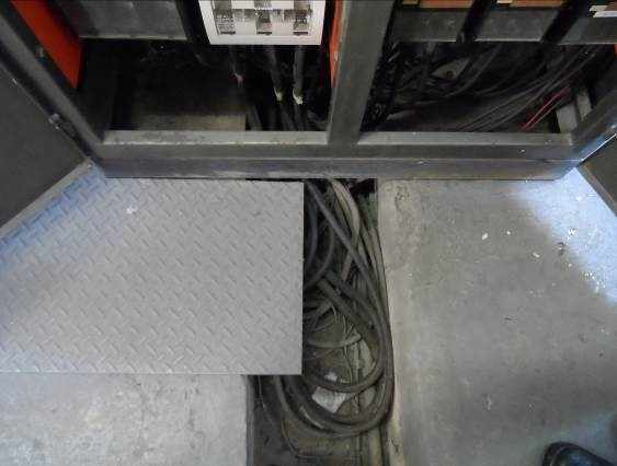
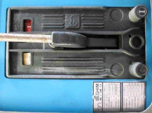
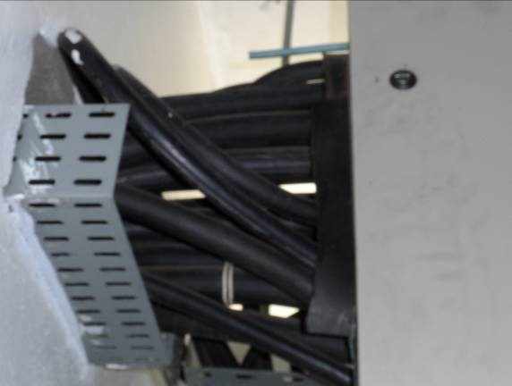
Occupancy rate of the Gutters: Note the following photos that portions of the submission made by gutters, are fully occupied, and there is the need, in case of return of the feeders, the expansion of the capacity of the referrals.
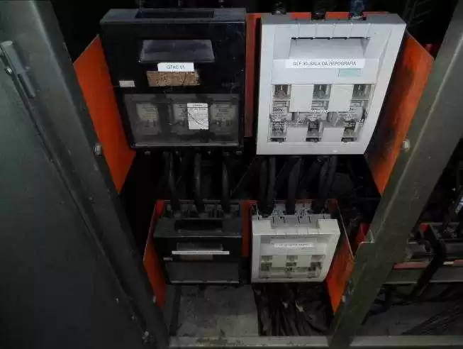
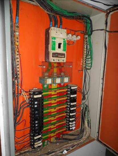
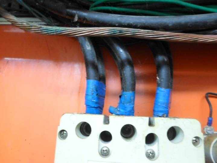
Picture of the old Refectory – QD1
The distribution table below appears to a certain age and you can't ensure the efficiency of its components. This picture, located inside the former refectory, has circuits that are not identified. To your power supply is given by means of 8 cables, derived table, two for each phase, as shown in the picture, beyond the neutral conductor, and the strand of grounding. Important to note that the circuit breakers, NEMA type, are relatively old, and, as already stated, it is not possible to say the degree of safety of installations.
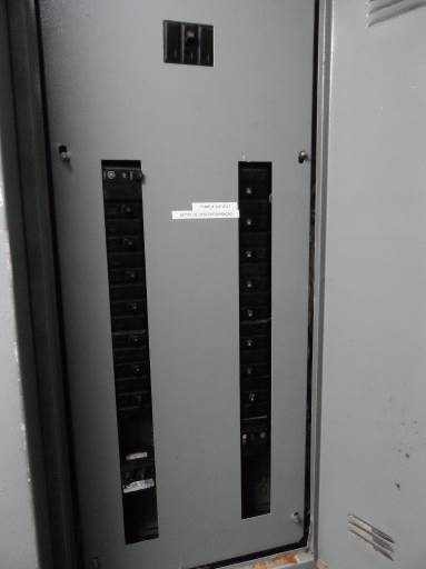
Switchbar QD1 QD2 derived from
The distribution table below appears to a certain age and you can't ensure the efficiency of its components. This picture, located inside the former refectory, has circuits that are not identified. Important to note that the circuit breakers, NEMA type, are relatively old, and, as reiterated, it is not possible to say the degree of safety of installations.
Electrical distribution: as said before, dedicated to meeting the cafeteria facilities and equipment shall be established.
Recommendation: the electric distribution will be based on the provisions of the layout. Lifting is required of all equipment and the identification of their consumptions for the specification of the shot.
Electrical installations (Sockets): The existing electrical installations are old, apparent and exposed, requiring complete replacement of circuits
Recommendation: in order to meet the standards for the installation of canteens, and recommended that the electrical installations are fitted, in order to facilitate the cleaning of the environments and allow earnings to aesthetic endeavor. Several points of General (TUG ´ s) and specific (TUE ´ s) will be deleted and/or redistributed as layout to be set by the administration.
Several tears in existing masonry will be made to embed the electrical installations so far apparent.
Electrical installations (lighting): trough type Luminaires without fall protection and explosion of lamps are arranged throughout the plant from the old cafeteria.
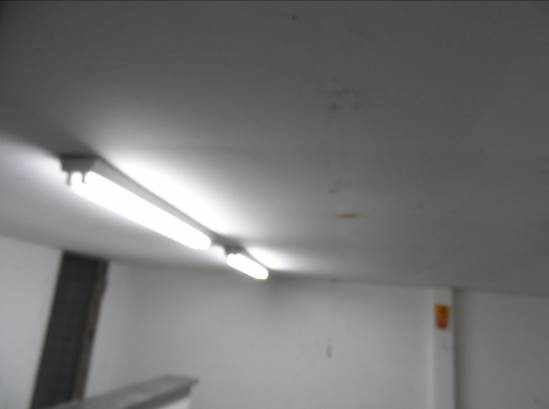

Recommendation: it is recommended to adopt, for the sizing of artificial lighting, the following proportions: Refectory-the artificial lighting level recommended for the area of the cafeteria is 150W/6 m ², for a maximum ceiling height of 3, 00 m, giving preference to the lamps LED type, due to durability, luminous efficiency and low consumption. For fluorescent lamps is recommended if the proportion of about 50W/6 m ² (for ceiling height of up to 3 meters); Kitchen, reception, Cleaning and storage – the level of artificial lighting suitable for the cooking area is 40W/4 m ² (for ceiling height of up to 3 metres).
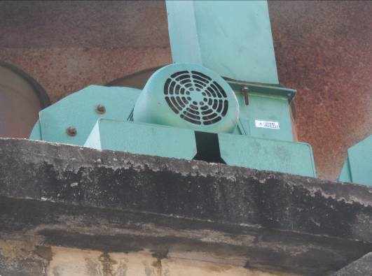
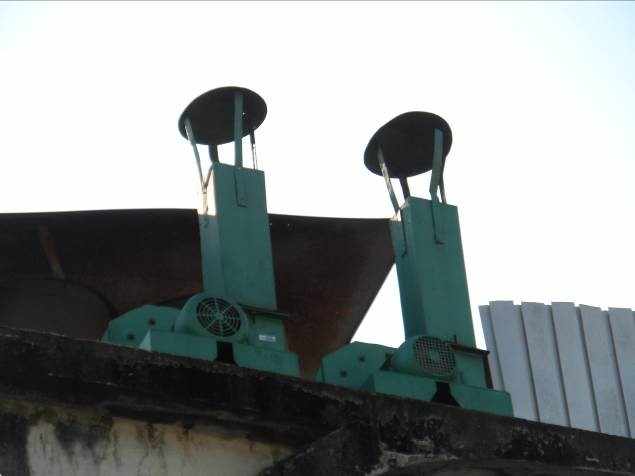
Electrical installations (motors):
The exhaust and ventilation System of the former kitchen of the cafeteria has 02 engines of which has no information about the operation and therefore, there is no way to guarantee the efficiency to serve on the exhaust system of the new restaurant to be possibly installed. You will need the revision or even the replacement of these engines. This is because they have key role in system that aims to promote the removal and treatment of gases and vapours arising from the process of cooking food, keeping the kitchen environment free of smoke and odors, as well as provide a constant air renewal maintaining the internal temperature within the limits of thermal comfort, desirable for a better performance from employees, according to ABNT NBR 14518, regulating the installation of ventilation systems for professional kitchens. Below is the picture of these engines.
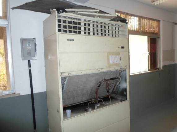
Electrical Installations (Cooling)
The electrical installation as well as the entire cooling system including the ducts, on the plaster lining, must be completely replaced. More cost-effective refrigeration appliances must be purchased.
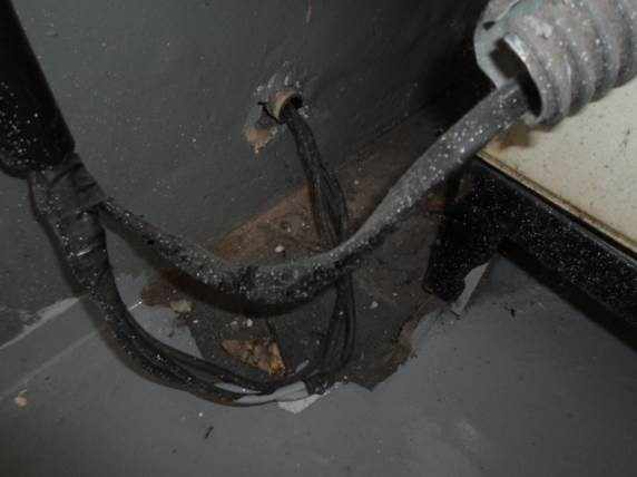
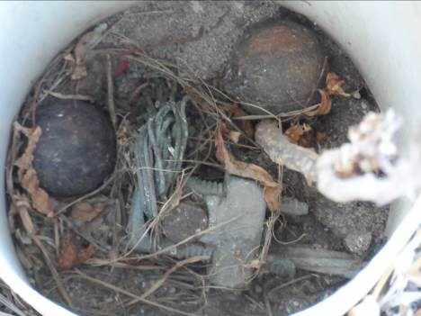
Ground loop: as mentioned, as were not presented electrical plants regarding current electrical installations exist in the building, it was not possible to say even about the existence, location and monitoring of grounding mesh. Two isolated stems were found on the right side of the building.
Recommendation: it is likely that should be established a new mesh of grounding for protection of equipment that are to be connected in the cafeteria, aiming at the protection of the equipments to be connected in the cafeteria as well as users, avoiding electrical shocks and indirect.
Project forecast AS BUILT: upon completion of the services, should be made the project as built of architectural and facilities (electric, gas, hidrossanitário and fire-fighting equipment and panic).
PRELIMINARY BUDGET PROPOSED
Prepared an estimated budget, which considering error margin of 20% to 15%.
- THE CIVIL PART COVERED:
- Technical team: provided for the hiring of expert engineer structure for monitoring and specialized in prophylaxis of structural problems, due to the complexity of electrical installations and hidrossanitária provided for hiring full and Civil Engineer electrical engineer.
- Demolition and removal: due to worn conditions of floor, wall covering and hidrossanitária facilities, decided to demolition and removal. In order to lessen the impact on structure chose to minimize the demolition of masonry, getting around 38, 88 m ².
- Fences and masonry: increase of 126, 32 m ² masonry, it should be noted that such walls are below the slab and would not overload, but rather, would relieve the distribution of loads of slabs and beams of the upper floor.
- Flooring and floor: Predicted the exchange floor due to excessive wear, patches and damage, being remade the baseboards, because there can be no edges or corners that accumulate dirt.
- Hidrossanitária facilities: due to problems with odors, sifonada box, leaks and sewer and water points modified, it is recommended to change the entire facility to be embedded in the wall and floor.
- Installation of gas: gas central placement with total change leaving pipe embedded in wall and floor.
- Frames: in order to suit the proposed layout provided for the exchange of some doors, but adjustment of the front frame.
- Vitreous Chinaware and metal: Predicted the exchange of metals and dishes which are damaged and adaptations to the new layout.
- Painting: considered the total painting with spaces being in epoxy paint, acrylic and synthetic enamel.
- Structural recovery: in order to meet the above in item III (recommendations and technical implications-civil Engineering), predicted structural recovery services with use of steel sheet for structural reinforcement, grout for recomposition of elements construction, epoxy base adhesive to fill cracks and cracks.
- Exhaust ducts and stainless steel parts: due to deterioration of existing ducts and stainless steel kitchen parts, quote for the installation.
Following the services and quantifying materials, preliminary budget level, obtained a value of materials and workmanship, with BDI included, R $597,424.49 (597,000, 424 reais and 49 Cents), worth exposed not the electrical installations that are detailed below.
- THE ELECTRIC PART COVERED:
Investments under the electrical installation and refrigeration are related and concentrated, mainly to study discrimination in hypothetical situations examined previously about the transformers and power supplies needed. The transformer installed must meet the total active power of the equipment used, but due to the presence of reactive power, your capacity should be calculated on the basis of the apparent power of the installations. Another increase is related to the creation of several power circuits of the electric charges and their systems of protection and control of equipment that grows with the increase of reactive energy, increase in capacity of TC's, TPS, etc. Similarly, to carry the same active power, without the increase of the losses, the section of the conductors must increase as the power factor decreases. The investment in the expansion of the Bank of capacitors, in order to correct this power factor to the value determined by the law, is not thrown.
Before all the problems and implications that were exposed in the report, the estimated costs for adequacy of electrical systems and cooling, except the purchase of industrial cooking equipment, is R $350,000.00 (350,000 dollars), already applied the BDI.
- TOTAL ESTIMATE OF THE COST OF DEPLOYMENT OF THE RESTAURANT:
Amounting to a total value, civil party added with electric, R $947,424.49 (947,000, 424 reais and 49 cents).
The budget was based on draft and consists of a preliminary analysis and may change when the Executive projects.
CONCLUSION
It is observed that there are two implications in use, first, the situation regarding the structural problem, because existence of restrictions of use and occupation of the property, the proposed measures should be taken, being possible to carry out the necessary adjustments.
Another question concerns the notification of the DVISA that shut the restaurant, the adjustments proposed in the preliminary draft, conform to the required under the two proposed layout for the restaurant. It should be noted that a preliminary analysis was carried out and that, for confirmation of layout and budget, will only be possible with the basic design.
The analysis of electrical implications covered since the substation until the final circuits, and may eventually need an expansion of the Bank of capacitors. Then, it will probably be necessary to replace the power supply cables, the general framework and components. It will still, in replacement of all existing cabling, creation of other circuits, LED type lamp replacement and removal of apparent installations. Exhaust system engines and their respective protections will be replaced.
As for the cooling system, the location has insufficient ventilation, refrigeration appliance in bad shape, exposed electrical wiring and ancient. Probably, it will require the deployment of a ground loop.
Before the above please note that there are two factors that contribute to a high cost of reform, the first the high degree of wear in the part of buildings leaving accumulation of repair services, and second, the large amount of constructive problems issued pathologies.
REFERENCES
BONATTO, Hamilton. Tenders and contracts of works and engineering services. Belo Horizonte: Forum. 2010. p. 198.
Brazil. Tribunal de Contas da União. Public works: basic recommendations for the hiring and supervision of public works. Tribunal de Contas da União. -2. Ed. Brasilia: TCU, SECOB, 2009.
MARCELLI, Mauritius. Accidents in construction: causes and remedies for damages in works/Mauricio Marcelli. -São Paulo: Pini, 2007
Souza, Vicente Custodio; Pathology, recovery and strengthening of concrete structures/Vicente Custodio Moreira de Souza and Tan Ripper. -São Paulo: Pini, 1998.
TAN, Technology, management, and quality Lutha on construction/Lutha Tan. -São Paulo: Editora Pini, 2001.
[1] Bachelor's degree in Civil Engineering. Federal University of Amazonas-Manaus Campus
[2] Bachelor's degree in electrical engineering. State University of Amazonas-Manaus Campus
[3] Bachelor's degree in Civil Engineering. Instituto Tecnológico de Aeronáutica
[4] Bachelor's degree in Civil Engineering. State University of Amazonas-Manaus Campus
[5] Bachelor's degree in Civil Engineering. Lutheran University Center of Manaus
[6] Bachelor's degree in Environmental Engineering. Universidade Federal de Rondônia-Campus Ji-Paraná
[7] Bachelor's degree in Civil Engineering. Federal University of Amazonas-Manaus Campus
[8] Bachelor's degree in electrical engineering. Universidade Federal da Bahia-Salvador Campus
[9] Bachelor's degree in electrical engineering. Federal University of Amazonas-Manaus Campus