SILVA, Dirceu Mateus da [1], SILVA, Wesley Nunes da [2], NASCIMENTOS, Daniel Junior Ferreira [3]
SILVA, Dirceu Mateus da; et.al. Use of PLC for Automatic Control in industrial processes. Multidisciplinary Core scientific journal of knowledge. 03 year, Ed. 06, vol. 02, pp. 56-83, June 2018. ISSN:2448-0959
Summary
In the process of leaching of a silicate metallurgical company, there is a production line that has manual operation, where operators perform all commands via manual valves. There were problems with waste of material and loss of income in the process due to automation and operational stability in production. Monitor the variables that compose this process is a safe way to ensure the performance of the production line and assertiveness in the parameters of acceptable limits. Based on the existing problems in the area, this study presents an alternative process control using the PLC (Programmable logic controller). The importance of making the monitoring of variables of level, flow, conductivity and pH is avoid waste occurred with transshipments of tanks and allows the optimization of the efficiency of the plant. At the end of the research are exposed the results obtained with the instrumentation system applied.
Key words: process, Instruments, efficiency, CLP.
Introduction
Process control is a field of engineering that has been increasingly enhanced through new technologies and tools that can be applied in any production process that is simple, in order to ensure greater productivity, optimize the operation time of the plants and production processes thus creating a greater yield.
Even with the great advances in industrial automation, there are still processes with some types of manual controls, which doesn't always guarantee maximum efficiency. With the use of measurement and control instruments it is possible to optimize the processes, providing a stable and reliable operation, with data available more easily.
However, this work aims to study a productive process by applying the concepts of process control, instrumentation and automation to propose an improvement of industrial control.
In the first chapter are the goals to be achieved with the development of the work and the methodological procedures used during the case study.
In the second chapter discusses the concepts about process control as well as the actions of control and characteristics of industrial processes.
The third chapter included a brief history of the emergence of automation and communication networks as well as your applicability in industrial environment.
In the fourth chapter is performed a literature review on some types of meters applied in industrial processes.
Chapter five behind the case study in a metallurgical company where one of your processes with manual operation, where were collected data to control application with instrumentation.
The sixth chapter shows the conclusions and recommendations obtained after the completion of this study and finally are the references used for the realization of the work and the annexes for the reader.
1.1 Questioning
Currently the plant of silicate leaching of a metallurgical company where was held the case study work with several steps of the process still relies on manual operations, i.e. direct intervention of the operator in the country, resulting in instability operational, loss of income, in addition to exposing the operator to an ergonomic posture ante. Seeking alternatives to improve the controls and consequently give greater profitability to the process, it was thought in automation of these operations, as well as the installation of measuring instruments and automatic control equipment that will eliminate the need for manual intervention.
Control and instrumentation of silicate leaching plant will allow the maintenance of the current level of zinc supply via silicate, improving plant efficiency and optimizing the operating time of the process.
1.2 Objectives
1.2.1 general objective
Develop control through measurement instruments to be part of the silicate leaching process making more precise dosage control and optimize the performance and production.
1.2.2 specific objectives
The specific objectives of the work are:
- Conduct literature review;
- Control of silicate leaching process through the programming logic according to the information received by the field instrumentation;
- Compare the performance of the process before and after the system of instrumentation;
- Provide a material for the deepening of theme, which could be the object of future studies for improving the process.
1.3 methodological procedures
The first action was the study and research on the theme of industrial instrumentation and process control where abstracts and reviews were carried out on the subjects. It was necessary to study the automation processes and communication networks in order to improve the knowledge on the topics.
The study was conducted in order to verify the possibility of application in the process control of silicate leaching in a metallurgical company of Minas Gerais-MG. For such study will be reviewed a boatload of continuous process where tanks are located eight tanks of zinc concentrate.
The knowledge of the process occurred from visits in the area to survey of existing problems, and then it was necessary to the collection of data and standards together with engineers and operators.
With the necessary data for the study were carried out several surveys to provide the best and most profitable possible applications for this process by checking that the automation will provide some positive feedback to the company. However, at the end of this project will be possible to verify the application of this reached the expected objectives and can be applied in industrial environment.
2. Process control
In the early days of human evolution, not known means of energy production. Thus, the energy was provided by human labor or animals that were domesticated. The industrial revolution started in Britain in the mid-18TH century brought the world the important technological changes and significantly impacted the production processes of the time, (7)
On the industrial revolution:
The Industrial Revolution began in England in the mid-18th century. Featured, basically, by the introduction of simple machines that have emerged for the replacement of muscular strength by mechanical and repetitive tasks performed by man. These productive activities have undergone an evolution faster, giving rise, in England, to the Industrial age. (12)
With the development of steam engines was possible to transform the raw energy into mechanical energy, and man evolved its processes when using accurately the mental work, which enabled the development of techniques to control new power source. From that moment, the manual labor began to be replaced by machinery and equipment, the replacement of manual control by automatic control of processes.
2.1 Concept and application
Process is a sequence of predefined steps and equipment determined in accordance with your functionality, that comprises a continuous processing of raw material in a certain goal. The processes can be manual or automatic operation. (2)
The control of a process is based on the interaction between components and instruments, from the configuration of a system, can show a desirable result of the controlled process. One can sum up a process control system basically in the following items: (8)
- Measuring element Detects changes in the process and provides a signal;
- Element of comparison: Compares a feedback signal with the reference measure, by supplying a command to the next stage to correct the difference detected in comparison;
- FIX: element Receives the command of the element of comparison and performs the necessary steps to work out the desired product;
- Final control element: device that acts directly on the process and tries to provide a constant output.
The control is mainly applied in industries that require precision and low level of failures, where the process is constantly measured (input) and the variable manipulated is changed by the controller, thus affecting the process and the end result. The advantage of having a controlled process, is that the output is systematized and maintains the standard quality and quantity as needed and also reduces the human effort, because the operation requires only the mental work or systemic.
2.2 Feedback
The Fed system is one that establishes a relationship between an output comparison and reference input, through instruments that perform the measurement of variables. This system uses the difference of output and input as a means to control the process. (8)
The signal comes from the comparison between the input and output can be called an error signal. When the feedback signal is subtracted from the reference signal is called negative feedback, and when the feedback signal is added to the reference signal is called a positive feedback. (3)
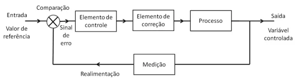
2.3 block diagram
To facilitate the identification of each component of the control systems, using a method called block diagram.
Block diagram of a system is a representation of the functions designed for each component and signal flow. The main components of a system are represented by blocks and are integrated through the lines that indicate the directions of flow of signals between the blocks. These diagrams are then used to represent dependency relationships between the variables of interest to the control. (7)
2.4 control types
2.4.1 Manual control and Automatic Control
Manual control is one that relies entirely on animal or human action in order to achieve a particular result or product. There's still that kind of control, especially in smaller companies, to small production or craft.
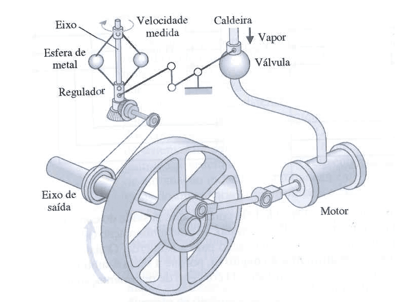
The automatic control is based on the use of instruments and system that have an error detector, actuator and control unit, allowing the operator, making accurate and continuous operation. James Watt was author of the first automatic controller with feedback, a regulator that ball was developed in 1769 and was used in industrial processes to control the speed of the steam engine. As it depicts the figure 1, the control was a mechanic and media output shaft speed of the engine, using the movement of the spheres to make the steam valve control, controlling so the amount of steam entering the engine. (5)
Spherical weights are pitched and move away from the axis of the regulator as the spindle speed of the steam engine's output increases, and through mechanical couplings, the steam valve closes and the motor slows down.
Figure 1 shows the regulator Watt ball. (5)
2.4.2 open loop Control
In an open loop system, process input is chosen according to the usual and experience, without using the method of comparison, in such a way that the result is the desired output. The output is not modified, and accompanies the process steps only under the conditions of operation, are controls operated by time base and not for feedback, as shown in Figure 2. (3)
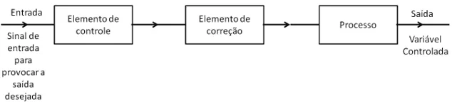
The basic elements (subsystems) of an open loop system are:
- Control element: This determines what action should be taken in order to control system entry.
- Fix element: He responds to the output signal of the control element and acts in order to position the controlled variable to the desired value.
- Process: is the plant system that offers the variable to be controlled.
In Figure 3 is represented an open loop control subsystem.
2.4.3 in closed loop Control
The main feature of a closed-loop control is feedback, which compares the output with the input of the process, where the output interferes directly in the control action. The output is always measured and compared with the input of the process to alleviate the flaws, reduce the rate of errors and ensure that the end result is satisfactory. Figure 4 displays an example of a closed loop. (7)
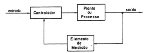
The basic elements (subsystems) of a closed loop system are:
- Element of comparison: Compares the reference value with the measured value and indicates the error showing how the output value is missing the expected value. The error is the same as the reference signal minus the measured signal.
- Control element: it provides the action to be taken in case of error.
- FIX: element Acts in order to fix the error, causing changes in the process.
- Process: is the system where the variable is controlled and provides the data.
- Measuring element: this element usually a sign which depicts the controlled variable and provides a signal fed back to the element that this element of comparison to check if there is any mistake.
Figure 5 exposes a closed loop example.
2.5 Drivers
The controller is the element which, in closed loop, has the function of receiving the error signal and generates an output that will be the input for the element. (5)
2.5.1 ON-OFF control action
Is the action of simpler and more common control, where there are only two positions for the final control element, normally closed or normally open, regardless of the intensity of the deviation or error. (7)
The main features of the on-off control are:
- The fix is independent of the intensity of the deviation;
- Does not fix the error of off-set;
- The gain is infinite;
- Causes oscillations in the processes.
2.6 Features of industrial processes
Process is a series of steps that evolves progressively, through a series of gradual changes in succession, with the goal of providing a product or a result. (7)
2.6.1 manufacturing processes
Continuous: In continuous process the goal or end product is obtained without disruptions in manufacturing, in one system.
Discontinuous: are known as batch process, which are made by steps and raw material inputs can happen after the cycles.
Monovariáveis: the monovariável process is one that has a variable and regulatory influences only a controlled variable.
Multivariate: multivariate process is one that has a variable and regulatory influence over a controlled variable. This type of process is prevalent in industrial means.
Unstable: Are processes that change their variables all the time, you can vary your pattern all the time.
Stable: it has a stability control, which remains constant, without many variations.
3. Industrial automation
Since ancient times human beings have been trying to make your life easier and practice, especially in work-related activities. At the end of the middle ages, caused by the huge advances that occurred at the time, weighed in on that machine could replace certain manual activities that were performed by humans. (10)
The earliest forms of development of the automation process occurred with the creation of control equipment and electrical and pneumatic measurement, but the automation gained wider prominence with numerical control machines in the years 50. These machines were made of valves and other electrical components that were soon replaced with transistors and integrated circuit boards.
The evolution happened quickly and soon the components were replaced by CNC (computer numerical Control) where all commands are given via computers, and thus integrate directly to CAD (computer aided design), allowing greater profitability, product standardization as design and agility in production, but the machines had high cost and being very fragile (10).
Over the years the CNCS were taking more and more space and gaining market, mainly in large and medium-sized industries, and, in the present day, the automated means dominate the market and are applied with communication networks and has been evolving every year, (10).
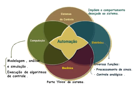
Automation is all process that requires minimal operator interference in activities, and these are carried out in a manner and of acting itself. The automation is an interdisciplinary area and is linked directly to Instrumentation, because the control and measurement instruments has an important participation in the automated processes. (11)
Figure 6 illustrates the automation concept showing your interdisciplinarity.
Currently the automation is not seen only as an option, but a necessity in large enterprises, because the market is increasingly competitive and newsy, which leads companies to invest in automated systems to gain time to activities related to the intellectuality and don't get stuck with menial services. Automation provides a considerable reduction in the cost of production, standardization of products, agility in fabrications, avoids wear of workers and provides ergonomic comfort to all users.
3.1 PLC-programmable logic controller
The programmable logic controller is one of the most process control devices used in industries. A CLP has the function of a programmable computer is used in industrial control systems and are designed to replace the large rooms of controls that before used relays. (9)
The PLC was established in 1968 under the name of MODICON. This name was derived from the name of your first manufacturer, Digital Modular Controller, and your Creator and inventor was Richard Morley. The idea of Richard was to build a more robust, reliable equipment, flexible and easy to handle and modification. (1)
The first process in which they used a CLP was in G.M., in a line of cars in various tests for calibration. In the early 70 very large developments occurred in microprocessor technology, the PLC's win flexibility and intelligence, improving the interface with the operator and earning ability arithmetic computational and communication data. Between the years 1974 and 1975 they won memory capacity, control of servomechanisms, control over inputs, outputs, analog variables and positioning. With these developments it was already possible to apply the PLCs in various areas of industry, making the process more simple, easy and cheap, are reduced with installations and electrical wiring. (1).
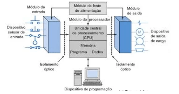
3.1.1 parts of a PLC
A PLC can be divided into parts, as shown in Figure 7, which shows the CPU central processing unit, input/output section, the power supply and the device.
There are two ways to incorporate the inputs and output of the PLC's: fixed and modulated. The i/o, input/output, fixed characteristics of PLCs of small businesses, where the processor and i/o are mounted together and have a fixed number of connections for inputs and outputs, as shown in Figure 8. (9)
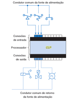
Fixed i/o has the advantage of low cost and the number of connections can be expanded, and a disadvantage is the lack of flexibility, because the amount and types of input is established by the unit.
In modular i/o modules are built separately and can be plugged in. This model consists of a rack, a power supply, a processor module, input/output modules, and an interface for programming and monitoring. The modules and the processor of the CLP are plugged into the motherboard and can communicate with all modules of the rack. Figure 9 shows the modular i/o.
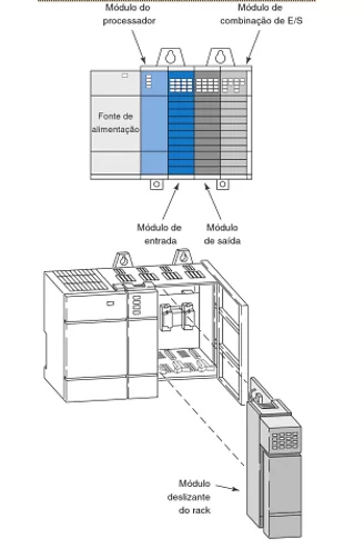
The power supply provides power to all the components that are plugged into the rack, and, for the largest PLCs is not used to feed with field devices, and by a source of DC (direct current) or AC (alternating current). (9)
The processor is the command of CLP and consists of a microprocessor for building logic and control communication between modules and requires a memory to store the results of logical operations. The CPU is responsible for receiving the logics that the user enters in ladder logic. "The CLP program is executed as part of an iterative process referred to as scan, in which the CPU reads the on or off State, and, after completing the steps in the program run the built-in Diagnostics and communication tasks" (9).
The programming device is used to insert the program in memory of the processor. The personal computer is the device used to elaborate the logics, usually in ladder, and can be transferred to the PLC via link or ethernet. The program is a series of commands developed according to the needs of the user.
3.1.2 operating principle of CLP
The PLCs have sequential operation doing a scan on the stages of the process, as shown in Figure 10, and when a step is being executed, the others are inactive. The total time spent for execution of the cycle is called clock.
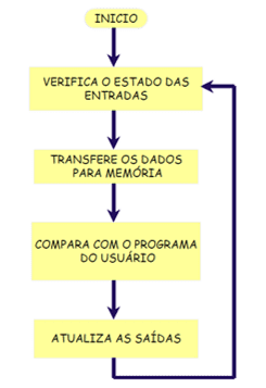
Each step is based on:
Start: at the beginning of the process, are verified the operating conditions of the CPU, memory, auxiliary circuits, in the keys, the existence of the program entered by the user, it issues a warning and error disables all outputs.
Checking the status of the inputs: in this step is read each entry in the process, checking to see if any occurred.
Comparison with the user program: the CLP updates the memory output image from the comparison with the instructions that the user entered in the program to start the entries.
Update: outputs the outputs are activated or deactivated according to the determination of the PLC and a new cycle is started. (6)
4. Case study
4.1 company overview
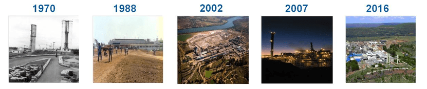
The case study was conducted in a metallurgical company in the State of Minas Gerais-MG, autoclave process and acid plant, which then started the process of expansion that, in 2001 where raised your production capacity of 110,000 to 160,000 tons of zinc . Figure 11 shows the development of factory during the years.
Is one of the largest global producers of zinc, being a world leader in the production of zinc oxide. It's the only zinc Metallurgy in the world with integrated treatment technology focused with different chemical qualities. The products of the process are:
- Zinc SHG – Used in the automotive industry, signs, appliances and electrical transmission towers.
- Zamac – Used in car engine parts and pressure die casting and centrifuged.
- Special alloys (Galfan, Zn4E, custom Alloys)-Used in electroplating in General, light poles and electrical transmission towers.
- Zinc powder-Used in paints and alkaline batteries.
- Zinc oxide — Used in rubber, cereals, yogurts, animal feed and cosmetics.
4.2 the process studied: silicate leaching
The object of this case study applies to silicate Leaching. This step of the production process has the function of solubilized zinc contained in concentrate-bearing silicate in the form of zinc sulfate by adding sulfuric acid solution. The leaching of zinc-bearing silicate concentrate initially should be made more lenient acidity due to acid reactions with carbonates present in the concentrate and, for total leaching of zinc is necessary increasing of acidity and residence time in tanks.
In table 1 are shown the chemical reactions that occurred in this step of the process:
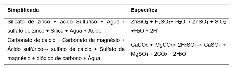
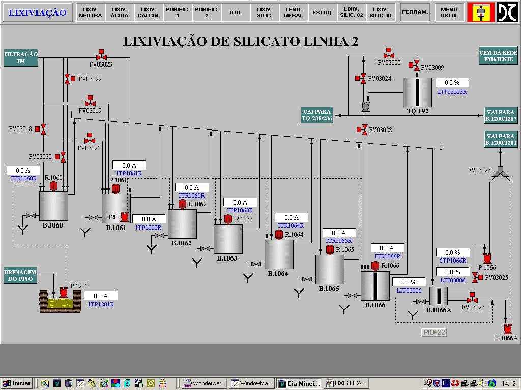
The process consists of a continuous as shown in Figure 12. The continuing consists of 8 tanks for the leaching process (b. 1060, b., b. 1062 1061, b. 1063, 1064, b. b. 1065, b. 1066, b. 1066A) and 1 solution tank attack (TQ-192). The tank b. 1060 receives spare power supply filtering zinc zinc, from there happens the leaching process, where the spare is just a tank to the other through gutters. The power flow is controlled by manual control valve.
To get to tank b. 1066, is inserted into the attack in the concentrated solution of zinc through a valve manual override, where the same is in residence for the reaction happen. After the time of residence'll concentrate for tank b. 1066A, where proceeds to another step of the process.
4.3 analysis of the problem
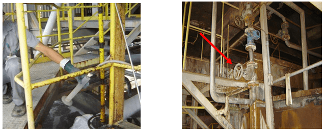
The quality and recovery of zinc sulfide is directly connected to the pH of the solution into the lime leaching process. The analysis of pH of the solution, it's manual mode, where the operator collects samples of solution directly in the process, every hour, and leads to the local lab to carry out the analysis. Depending on the outcome of the sample, is required the addition of sulfuric acid solution to improve the quality of zinc sulphate.
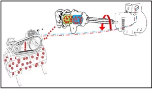
The dosage of sulfuric acid (also known as attack solution) is carried out in manual mode, where the operator acts directly in the process, opening and closing of control valves. Dosing procedures are not always reliable and accurate, this compromises the end result of zinc recovery. Figure 13 shows how samples are collected for measurement of pH and manual control valve located in the process.
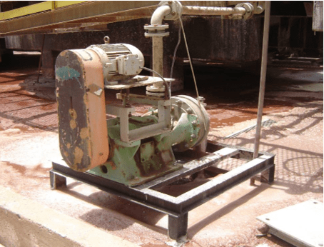
A major problem encountered in this step is the amount of transfers because the production process be based in flotation system, where the zinc sulfide goes from tank to tank through foaming. The operation of the well pump containment basin of silicate leaching has the operation dependent on the operator's command, which causes a constant work of checking the local situation. Figure 14 shows the manual control pump in process.
The stability of the process is necessary for the quality of the final product, achievement of clients ' specifications and avoid losses during the flotation process, what the manual process doesn't always guarantee. Avoiding losses in the process, it is possible to increase the yield of silicate leaching plant, some variables can be controlled:
- If the tank level rises until the transfer, it is necessary to apply a tank level monitoring to prevent the problem and avoid waste in the process.
- If the dosage of the attack is performed according to the levels of acidity of concentrated, pH control is required and conductivity to the commands of dosage are carried out according to the variation of these variables, thus avoiding loss of recovery of zinc.
- If the input flow monitoring of tanks, you can adjust the material input automatically according to the values and their variations, thus ensuring that the material is in your ideal range.
4.4 application of control
To prevent transshipment hubs and increase the yield of silicate leaching plant, is required the installation of instruments for measurement and control of pH, conductivity, flow and level, as well as control valves.
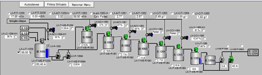
Measuring instruments were installed and control as follows (as shown in Figure 15):
- Installed flow control solution supply line of attack, where the registration and transmission with PLC/field/PLC interface.
- In all tanks were installed a closed loop for valve actuation, the device is mounted on the main control panel, this sends a signal via the network to the air control valve and is connected to the installed instruments in the field.
- At the exit of tanks B. 1060, b. and b. 1062 1061 were installed closed meshes of measuring pH, which send a signal via the network to the PLC to perform the command.
- At the exit of the tanks b. 1063, 1064 and b. b. 1065 were installed closed meshes concentrate conductivity measurement, which send a signal via the network to the PLC to perform the command.
- In the tank b. 1066A was installed a level control loop that communicate with the pumping of containment and thickener, which carries the material to continuity of the process.
- The concentrate makes your residence time in the tanks b. 1066 and b. 1066A.
All instruments were interconnected system Foundation Fieldbus network.
Used the instrument of ultrasonic type level measurement that performs well in viscous materials that the zinc concentrate. The flow meter used was the electromagnetic type of insert.
The pH meter used consists of the traditional comparison method for measurement and reference electrode, and the inductive conductivity meter that has great performance dealing with the process material. Applied valves for modulation system.
4.5 Results
In front of the studies and applications, it is concluded that the instrumentation and control system of lime leaching step provided better performance to the process. The measurement and control of acidity ensures a good zinc leaching contained, avoids dilution of the zinc in the plant if the concentration is below the specified. The precise control of the pH with parameters for each tank, provided greater zinc recovery and reduce use of attack.
Charts 1 and 2 the following are samples of the logbook. In them we can identify a significant improvement in the stability of the process and efficiency of the plant.
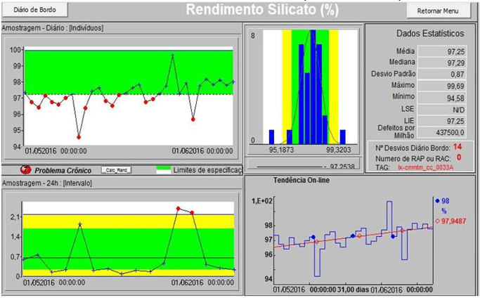
Notes in chart 1 that, in the period of one month (01/05/2016 the 01/06/2016) 14 deviations occurred, a standard deviation of 0.87 and average yield of 97.25%. This was the situation prior to the installation of measuring instruments and control.
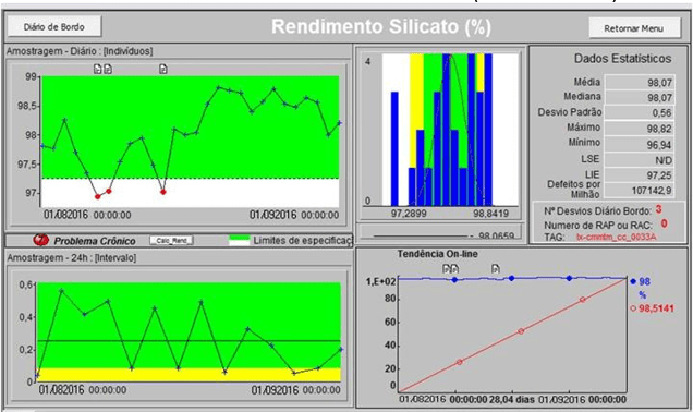
After installing the instrumentation system, one can observe in the graph 2 that, in comparison with the period without the installation of instruments, there were 3 deviations in the same time range (01/08/2016 to 01/09/2016), the standard deviation fell 0.87 to 0.56 and average revenue rose to 97.25% to 98.07%. There was an improvement in the stability in the process, because the yield has remained in the range expected for a longer period, which is a situation relevant to the production.
With everything, the process control system applied to the studied plant had a gain of 0.82 percent yield, that, in view of the volume of production end of 151,500 zinc t/year, corresponding to 1,242.3 t/year.
The current price of the ton of zinc according to the LME (London Metal Exchange) is $ $1,981.00 and the cost of production is ± $ $1,300.00. Considering the cost of deployment of the automated system of ± $734.00 .00, that dissolves in cost approximately 10.4 months, taking into account the stable income and according to the reference month, making feasible and satisfactory implementation of this System.
Final considerations
On of the above with the case study, the process control system through the use of the CLP has influence over some points relevant to the process:
- Automation of silicate leaching;
- Income gain on plant;
- Reduction of waste in the process.
With the automation of the process is done the dosage control of attack in the process, allowing better recovery of zinc in silicate concentrate, bringing increase in final production of zinc. The improvement of income can be checked in the comparison charts 1 and 2, which shows the performance improvement behind the logbook with evidence from the period of one month.
Automation enables also the operator's convenience, you can view all events of the supervisory process via and can perform commands from it, without the need of assistance directly in the process, minimizing the risk of accidents with the operator, once, was exposed to the risk of being hit by chemicals and dangerous.
With the use of the PLC was unable to monitor all the important variables for the smooth operation of the plant, with the level control you can monitor the tank to avoid waste in the process, ensuring maximum utilization. The instrumentation allows for reliable data collection, but need preventive maintenance and calibrations for your proper functioning.
Therefore, the process control through the CLP allows better stability in industrial processes, in the case of the process studied, made possible the increase of income of silicate leaching plant, which can dilute the investment generated with the the installation process, making it viable and profitable in a short time after deployment.
References
1. BEGA, Egidio Alberto. Industrial Instrumentation. 2 ed. Rio de Janeiro: 124 P, 2006.
2. Bernardo Ferreira Nivaldo. Process utilities. São Paulo: Tests-jeanrenard, 2013.
3. BOLTON w. control engineering. Translation: Valcere Vieira Rocha e Silva. Publisher: Makoron Books. São Paulo .1995.
4. BOLTON w. Instrumentation and control. Translation: Luiz Alberto de Gandhi Vidal. Publisher: Hemus. São Paulo, 2002.
5. COSTA, Luiz Augusto a. specifying Industrial automation systems. 1 ed. December 2011.
6. Richard C DORF, Robert H BISHOP. Modern control systems. 11 ed. LTC Publisher. Rio de Janeiro, 2009.
7. EURIPIDES, Maes. Industrial Automation Engineering course. 2007. 73 f. Monograph (Specialization)-Industrial Automation course course, Eep-engineering school of Piracicaba, Cotip, Piracicaba, 2007.
8. Adalberto Luiz de OLIVEIRA Lima. Fundamentals of process control. SENAI. Esperito Santo. 1999.
9. Alberto Luiz de OLIVEIRA Lima. Instrumentation – Final control Elements. Senai. Esperito Santo, 1999.
10. OGATA, Katsuhiko. Modern control engineering. 4 ed. Publisher Pearson. São Paulo, 2010.
11. PETRUZELLA, Frank D. Programmable Logic Controllers. 4 ed. Publisher Bookman. 2012
12. ROSARIO João Maurício. Industrial Automation. 2 ed. Publisher Baraúna. São Paulo, 2009.
13. RIBEIRO, Marcos Antônio. Instrumentation. 8 ed. Salvador, 1999.
14. RIBEIRO, Marcos Antônio. Instrumentation and automation to operator. 1ed. Salvador, 2002.
15. SILVEIRA Paulo Roberto da, SANTOS, Marie e. Automation and control discrete. 9 ed., São Paulo: Editora Erica, 2010.
[1] Degree in electrical engineering – FPM 2018.
[2] Electrical engineer-FPM 2018.
[3] Systems analyst-FPM 2018.